Explaining Voltage Split in Series Circuits with Ohm's Law

AI Thread Summary
In a series circuit with two resistors, the voltage from the battery is divided equally between the resistors due to Ohm's Law, which states that voltage drop across a resistor is proportional to its resistance. When a battery of 8V is introduced, each resistor experiences a voltage drop of 4V because they have equal resistance, resulting in a common current that splits the total voltage. The discussion highlights that while Kirchhoff's voltage law explains the experimental result, it does not address the underlying mechanism of voltage division. Additionally, the transient response of the circuit, influenced by parasitic elements like capacitors and inductors, plays a role in how quickly the circuit reaches steady state. Ultimately, understanding the voltage split requires recognizing the limitations of simplified circuit models and the complexities of electromagnetic behavior.
JD_PM
Messages
1,125
Reaction score
156
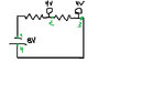
Let us set up a very simple circuit, with two resistors in series as shown in the sketch.

SimpleINSERIEScircuit.png


We know that for this particular circuit ##V_{14} = V_{12} + V_{23}##. But what I have always wondered is:

How does the circuit "know" that once I introduce a battery of ##8 V## that each of the bulbs will yield ##4V##?

I remember asking a similar question back in my bachelor years (general physics III course) and getting an answer like "due to Kirchhoff's voltage law: The sum of the potential differences around any closed loop is zero" but, in my opinion, this does not answer the question. Kirchhoff's law explains the experimental result but my question is more about how does the circuit manage to split the ##8V## of the battery into ##4V## volts for each bulb.

We all agree that switching on the battery and the split does not happen simultaneously.

My question, in other words, is: how can the split be explained?

Thank you! :biggrin:
 

Attachments

  • SimpleINSERIEScircuit.png
    SimpleINSERIEScircuit.png
    1.7 KB · Views: 129
Engineering news on Phys.org
JD_PM said:
How does the circuit "know" that once I introduce a battery of 8V that each of the bulbs will yield 4V?

1635699424908.png

I'll let others address your question, but I do want to clear up your notation. You should be sure to indicate with the indices on those voltages that the voltage gain due to the battery equals the sum of the voltage drops across the resistors, so write it this way:
$$V_{14} = V_{32} + V_{21}$$
 
JD_PM said:
We all agree that switching on the battery and the split does not happen simultaneously.

My question, in other words, is: how can the split be explained?
If you cut an apple in two, do you demand explanation that you now have two pieces. Your question makes no sense to me.

In circuit analysis, the type of analysis that you use when you draw a circuit like that. KVL and KCL are satisfied instantaneously and continuously. There is no delay. There is no first, then second reasoning valid.
 
You must always keep in mind the Electrical Engineering is a field mostly defined by approximate solutions to incredibly complex Electromagnetic systems. In order to understand the limitations of the simplified models we use (like lumped element circuits), it is really, really, good to learn some physics.

The pedantic answer is nothing happens "simultaneously" in this universe, as Einstein explained in special relativity.

But, at a more practical level, all circuits contain "parasitic" elements, usually small capacitors and inductors, that are left out of the schematics so we can focus on the salient features we want to communicate or analyze. In this medium complexity framework, the energy that you must put into the electric fields of the capacitors and the magnetic fields of the inductors will slow the transient response. You can think of this as the circuit "charging up" to it's behavior described by the simplistic circuit shown. For a circuit like this it may take 10's of nsec to do this, which is often irrelevant compared to the time scale that the designers care about; or not, it all depends on what you are trying to achieve and how you want to model the real world.

By giving you such a simple model of the electronic system, they are telling you to ignore all of the complexities they have left out.

For an even simpler explanation, you can think of "trial and error", the circuit does takes some time to get it right.
 
When you make the last connection, an EM wave travels from that point along the two wires to the furthest point of ther circuit. It is actually the leading edge of a step function, and after several dimishing reflections back and forth it establishes the steady state conditions in the circuit.
 
  • Informative
Likes berkeman
What @DaveE and @tech99 said is correct, but when you model things with EM waves, and distributed capacitances and inductances between wires, you can no longer use Ohm's Law plus Kirchhoff's Laws to analyze it. Therefore the voltage splitting question in your OP applies only to the simple case circuit case, not the advanced fields cases.

Many students make that error. They want to be able to sketch simple circuits and use the simple solution techniques, but to bring in deeper concepts like fields, charged particles, and distributed parameters. Unfortunately, they don't mix well. You need other analysis methods and different reasoning for the advanced cases.
 
  • Like
Likes DaveE and hutchphd
JD_PM said:
My question, in other words, is: how can the split be explained?
You can explain it with Ohms law.
The total resistance is 2·R, the voltage is V;
So by Ohms law the common current is I = V / ( 2·R );
The voltage dropped across one R will be Vr = R · I;
∴ Vr = R · V / ( 2·R ) = V / 2.
The voltage is divided proportionally because the current is common to both resistors.
 
Back
Top