I'll fix up your LaTeX by replacing each occurrence of [ tex ] and [ \ tex ] with a double #.
It is clearly not valid to conclude that F=0. Such a structure could be created and a force F applied and yet the structure resist movement.
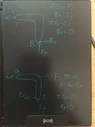
I am having trouble guessing what your labels for forces mean. Please state for each, what it acts on, at which point, and in what direction as positive.
jojosg said:
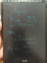
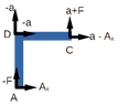
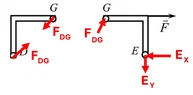
Member BE:
##\sum F_x = 0 \quad \Rightarrow \quad \frac{F_G}{\sqrt{2}} = F + E_x##
You've lost me already. By "member BE" do you mean the L shape from B to C via E? It'll be clearer to call that BC, since there is no label on the angle in DG or EG.
But if you do mean BC, F does not act directly on it.
What exactly is ##F_G##? And why divide it by ##\sqrt 2##?
jojosg said:
##\sum F_y = 0 \quad \Rightarrow \quad E_y = \frac{F_G}{\sqrt{2}}##
##\Rightarrow F_G = \sqrt{2}E_y##
From this, it looks like you are defining ##F_G## as the total force DG exerts on EG and assuming, without justification, that it acts at 45° to the horizontal.
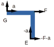
How about this notation for the forces:
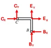
At a junction J between two L shapes, ##J_x## and ##-J_x## are the horizontal forces they exert on each other, to the right being positive; ##J_y## and ##-J_y## are the vertical forces, up being positive. Adopt the convention that ##J_x## is the force the lower (lefthand) shape exerts on the upper (right hand) shape.
E.g. at E, BC exerts ##E_x## and ##E_y## on EG. It doesn’t matter if it turns out that BC pulls down on EG: that will simply produce a negative value for ##E_y##.
I see no point in reading further till we get these issues sorted.
jojosg said:
From equilibrium: ##E_y = F + E_x##
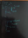
Member BC:
##\sum F_x = 0 \quad \Rightarrow \quad B_x = E_x + \frac{F_C}{\sqrt{2}}##
##\sum F_y = 0 \quad \Rightarrow \quad B_y = E_y + \frac{F_C}{\sqrt{2}}##
With substitution:
##B_y = F + E_x + \frac{F_C}{\sqrt{2}}, \quad B_x = E_x + \frac{F_C}{\sqrt{2}}##
Substituting ##E_y = F + E_x##:
##B_y = F + E_x + \frac{F_C}{\sqrt{2}}##
##B_x = E_x + \frac{F_C}{\sqrt{2}}##
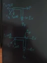
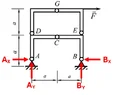
Joint B/Whole Structure:
##\sum F_y = 0 \quad \Rightarrow \quad A_y + \frac{F_D}{2} + \frac{F_C}{2} = 0##
##\sum F_x = 0 \quad \Rightarrow \quad A_x + \frac{F_C}{2} + \frac{F_D}{2} = 0##
Given ##A_y = A_x = 0##:
##\frac{F_G}{\sqrt{2}} - \frac{F_D}{\sqrt{2}} = 0, \quad \frac{F_G}{\sqrt{2}} = \frac{F_D}{\sqrt{2}}##
Moment about B:
##\sum M_B = 0 \quad \Rightarrow \quad -F(2a) = 0 \quad \Rightarrow \quad F = 0##
Thus:
##B_x = E_x + \frac{F_C}{\sqrt{2}}##
##B_y = E_x + \frac{F_C}{\sqrt{2}} \quad \text{(since } F = 0\text{)}##
Member BE:
##\sum F_x = 0 \quad \Rightarrow \quad \frac{F_G}{\sqrt{2}} = F + E_x##
##\sum F_y = 0 \quad \Rightarrow \quad E_y = \frac{F_G}{\sqrt{2}}##
##\Rightarrow F_G = \sqrt{2}E_y##
From equilibrium: ##E_y = F + E_x##
Member BC:
##\sum F_x = 0 \quad \Rightarrow \quad B_x = E_x + \frac{F_C}{\sqrt{2}}##
##\sum F_y = 0 \quad \Rightarrow \quad B_y = E_y + \frac{F_C}{\sqrt{2}}##
With substitution:
##B_y = F + E_x + \frac{F_C}{\sqrt{2}}, \quad B_x = E_x + \frac{F_C}{\sqrt{2}}##
Substituting ##E_y = F + E_x##:
##B_y = F + E_x + \frac{F_C}{\sqrt{2}}##
##B_x = E_x + \frac{F_C}{\sqrt{2}}##
Joint B/Whole Structure:
##\sum F_y = 0 \quad \Rightarrow \quad A_y + \frac{F_D}{2} + \frac{F_C}{2} = 0##
##\sum F_x = 0 \quad \Rightarrow \quad A_x + \frac{F_C}{2} + \frac{F_D}{2} = 0##
Given ##A_y = A_x = 0##:
##\frac{F_G}{\sqrt{2}} - \frac{F_D}{\sqrt{2}} = 0, \quad \frac{F_G}{\sqrt{2}} = \frac{F_D}{\sqrt{2}}##
Moment about B:
##\sum M_B = 0 \quad \Rightarrow \quad -F(2a) = 0 \quad \Rightarrow \quad F = 0##
Thus:
##B_x = E_x + \frac{F_C}{\sqrt{2}}##
##B_y = E_x + \frac{F_C}{\sqrt{2}} \quad \text{(since } F = 0\text{)}##
 I tried calculate moment about a which is 2a(By + Bx + Ey + Ex +F) + a (Gy + Gx + Cy + Cx). But I don't think I'm correct, any help would be appreciated, this was a question on a final exam paper in my Mechanics course.