Heat Flow in a Pipe with integrated Sensor

In summary, the conversation discusses a problem with a setup involving a main pipe and a branch pipe with a sensor at the end. The fluid initially flows through the pipes at a temperature of 25°C, but is then heated to 350°C while still flowing. The conversation also addresses how to calculate heat exchange between the flowing and standing medium, the type of fluid being used (oil), and the possibility of using a pigtail to reduce convection and conduction. The main concern is preventing the temperature at the sensor from exceeding 120°C, with suggestions for using a long coil of capillary tube or an isolating diaphragm. The conversation concludes with the recommendation to do some testing and use a pigtail to protect the sensor from direct
  • #1
Teru123
8
1
Hello,
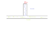
I have the following problem and hope you can help me. I have the setup as shown in the drawing. A pipe that is flowed through, and in the middle of it another pipe, but at the end of this branch is a sensor. Initially the fluid would flow, with a temperature of 25°C. If my thought is correct, the pipe with the sensor (if there is a drain valve) would fill with the liquid and then rest, because there would be no more flow, since it has nowhere to flow.
Now the liquid is slowly heated (heating to about 350°C) and continues to flow the same way. How would the temperature in the branch change? This would have to be still relatively cold at the sensor, since no exchange of the liquid takes place, since no flow is present in the branch, or do I have there a mistake in my thought?
How would you calculate the heat exchange between the flowing and standing medium? Because there is heat exchange only there, which would then have to be "up" through the entire water column. Can we calculate this in a simplified way as forced convection on a plane wall and assume the fluid portion in the branch as a plane wall?

I hope the problem is apparent, because I would need to calculate the length of the branch so that a certain temperature at the sensor is not exceeded.
Thanks a lot!
 

Attachments

  • Rohr.png
    Rohr.png
    2.9 KB · Views: 116
Engineering news on Phys.org
  • #2
Welcome!
What is that sensor sensing?
 
  • #3
Hey,
The sensor is sensing the pressure. The sensor should be low cost, that's why i need to reduce the Temperature at the end of the Pipe where the sensor is.
 
  • #4
Unless the branch pipe is externally cooled, you can't prevent it from eventually equalizing with the flowing main pipe.

What is the fluid?
 
  • #5
The Fluid is Oil. The pipe isn't externally cooled, but is very thin and long, so the heat would be exchanged with the surronding air wouldn't it? So theroetically it wouldn't equalize, or am i wrong?
 
  • #6
To simplify it I wantet to calculate the Temperature by the Sensor with the thermal restistance of the resting oil in the capillary and ignore the convection. Or is my thought to simplified?
 
  • #7
Teru123 said:
The Fluid is Oil. The pipe isn't externally cooled, but is very thin and long, so the heat would be exchanged with the surronding air wouldn't it? So theroetically it wouldn't equalize, or am i wrong?
If it isn't insulated then heat exchange with air is "externally cooled".

This would be a very difficult problem to accurately solve analytically.
 
  • Like
Likes DaveE
  • #8
It doesn't really need to be accurately solved. Just approxmatley the length of the Pipe that needs to be installed so that the temperature doesn't exceed 120°C when it reaches the sensor. So i know how much pipe i need or if its possible to do.
 
  • #9
Or do you think it is easier and better to just buy a pipe and measure the Temperature instead of calculating it? Like a trial and error thing.
 
  • #10
Teru123 said:
Or do you think it is easier and better to just buy a pipe and measure the Temperature instead of calculating it? Like a trial and error thing.
Definitely, yes.
 
  • Like
Likes Teru123
  • #11
russ_watters said:
This would be a very difficult problem to accurately solve analytically.

Teru123 said:
Or do you think it is easier and better to just buy a pipe and measure the Temperature instead of calculating it? Like a trial and error thing.

russ_watters said:
Definitely, yes.

I agree with @russ_watters . If possible do some testing.
 
  • Like
Likes Teru123
  • #12
Lnewqban said:
Welcome!
What is that sensor sensing?
Teru123 said:
Hey,
The sensor is sensing the pressure. The sensor should be low cost, that's why i need to reduce the Temperature at the end of the Pipe where the sensor is.
In that case, I would use a long coil of capillary tube, while independently supporting the sensor weight.
That would reduce convection through oil and conduction through metal., while increasing the surface for radiation into the surrounding air.

If the direct contact of the hot oil could damage the sensor, an isolating diaphragm could help.
Please, see:
https://instrumentationtools.com/pressure-gauges-remote-and-chemical-seals/

Bourdon-tube-pressure-gauge-with-remote-seal.png
 
Last edited:
  • Like
Likes erobz, Teru123 and russ_watters
  • #13
This is a common problem in plants with high pressure steam lines. They mount the pressure sensors/gauges on a pigtail. This is a pigtail:
Pigtail.jpg

And a link to the pigtail page from a manufacturer of pressure gauges: https://www.ashcroft.com/products/pressure/accessories/1098-1100-siphons/. This is not the only manufacturer that makes pigtails, it is one of the first web sites that came up when I searched using search terms pressure gauge pigtail.

Teru123 said:
This would have to be still relatively cold at the sensor, since no exchange of the liquid takes place, since no flow is present in the branch, or do I have there a mistake in my thought?
Your thought is correct. The straight portion of the pigtail should be long enough to extend through the pipe insulation. The curved portion should be outside the pipe insulation. Since you are starting with room temperature oil in a pressurized line, then slowly heating the flowing oil, the pigtail will fill the cool oil. Heat transfer to air will be large enough, and conductive heat transfer through the oil will be low enough, that the pressure gauge/sensor will not get very hot.
 
  • Like
Likes Teru123, russ_watters and Lnewqban
  • #14
Thanks for your answers! A Pigtail was also my first thought but the companies i contacted said it wouldn't cool the oil enough so that wasnt an option. I should use a capillary that is very thin and long.

My idea now was to simulate the Heat flow in a capillary in ANSYS. Do you think it is better (and easier) to simulate the heat transfer using ANSYS first? I don't really know how much effort it is to make a simulation like that, because it would be my first time using ANSYS.
 
  • #15
Teru123 said:
I don't really know how much effort it is to make a simulation like that, because it would be my first time using ANSYS.
RTFM! (Read The Fine Manual)

My bet is that by the time you understand ANSYS enough to actually use it, your salary and overhead will have cost more than trying a few things to find one that works.

(That's my 2 cents worth of approach anyhow. :oldwink:)

Cheers,
Tom
 
  • Like
Likes Teru123
  • #16
Teru123 said:
It doesn't really need to be accurately solved. Just approxmatley the length of the Pipe that needs to be installed so that the temperature doesn't exceed 120°C when it reaches the sensor. So i know how much pipe i need or if its possible to do.

You say the pipe is thin... how thin? , Is it metal or plastic? In a reasonably thick walled metal pipe, you can neglect thermal gradients across the pipe wall because of the high thermal conductivity( 400 ## \rm{\frac{ W } { mK} }## ). But in PVC ( 0.25 ## \rm{\frac{W} {mK} }## ) with its low thermal conductivity the internal flow may be at a significantly higher temperature than the outside of the pipe.

For the metal pipe, (normal relative thickness):

$$ \ln\left( \frac{ \Delta T_o}{\Delta T_i} \right) = - \frac{P L}{\dot{m} c_p} \bar{h_L} $$

Where:

## \Delta T_o ## is the temperature difference between the temperature of the surroundings ## T_s ## ( assumed constant ), and the fluid temperature at the outlet.

## \Delta T_i ## is the temperature difference between the temperature of the surroundings ## T_s ## ( assumed constant), and the fluid temperature at the inlet.

## P## is the perimeter of the pipe.

## \dot{m} ## is the mass flow rate of the fluid.

## c_p ## is the specific heat of the fluid

## \bar{h_L} ## is the average convection coefficient of the surroundings/pipe

So you calulate/plug in the appropriate values and solve for ## L ## the length of the pipe.
 
  • Like
Likes Teru123
  • #17
For any (circular) pipe with a wall thickness ## r_{ext} - r_{int}## I'm coming up with:

$$ \ln\left( \frac{ \Delta T_o}{\Delta T_i} \right) = - \frac{2 \pi L}{ \dot{m} c_p} \left( \frac{1}{\bar{h}_{int} } + \frac{ \ln \left( \frac{ r_{ext}}{ r_{int}} \right) }{k} + \frac{1}{\bar{h}_{ext}} \right)^{-1} $$

Where

## \bar{h}_{int} ## is the average convection coefficient between the oil and the pipe interior wall

## \bar{h}_{ext} ## is the average convection coefficient between the pipe exterior wall and the surroundings

## k ## is the thermal conductivity of the pipe material

and

## r_{int}, r_{ext} ## are respectively the interior and exterior radii of the pipe.

The problem with using either of these methods is error in convection coefficients (they are basically a best guesses) as well as errors in mass flowrate. If there is a pump ( or even if its draining from a tank under gravity), as you increase the length of the pipe the mass flow rate will decrease from viscous effects i.e. the mass flow rate ## \dot{m} ## is also a function of ## L ##. This was not accounted for, it could be, but things start to get messy pretty quick.

Is cooling the oil a primary objective, or just not to damage the sensor? If its the latter, then as others have pointed out, it can be isolated with some engineering. If you have to cool the oil, it still might be best to pass it through a compact heat exchanger. If its traveling to a remote location, then maybe the long pipe passively cooling it on its way makes sense economically.
 
Last edited:
  • Like
Likes Teru123
  • #18
For still air I'd use something like:

## \bar{h}_{ext} = 10 \rm{\frac{W}{m^2 K}}##

For the oil/pipe convection coefficient (maybe) ## \bar{h}_{int} = 300 \rm{\frac{W}{m^2 K}}##

That should get you in the ball park.
 
  • Like
Likes Teru123
  • #19
erobz said:
If there is a pump
@erobz, the OP is asking about a closed-ended branch line to a pressure sensor. There is no forced flow through this line. Any internal convection flow would have to be some kind of annular flow "up" with return flow "down" the center of the tube. As far as I know, that is not going to be analyzed well with the models you are showing.

To answer the OP, I would stick with the recommendation to try different length tubing and measure the temperature gradient. Another approach would be to find a similar configuration in use and copy it.
 
  • Like
Likes Teru123
  • #20
gmax137 said:
@erobz, the OP is asking about a closed-ended branch line to a pressure sensor. There is no forced flow through this line. Any internal convection flow would have to be some kind of annular flow "up" with return flow "down" the center of the tube. As far as I know, that is not going to be analyzed well with the models you are showing.

To answer the OP, I would stick with the recommendation to try different length tubing and measure the temperature gradient. Another approach would be to find a similar configuration in use and copy it.

Sorry, I missed what they were trying to explain, and just went with what seemed apparent from the "arrows" from the process diagram!

You can still do an analysis of this as a "cooling fin"

Since the tube is thin, metal we ignore thermal gradients across the pipe wall. The surface temp of the pipe at position ## x ## should be the same as the temp of the fluid at position ##x##. Using the following tip condition:

## h \theta(L) = - k \left. \frac{d \theta }{dx} \right|_{x= L} ##

Then;

$$ \frac{T(x) - T_{s}}{ T(0) - T_{s} } = \frac{ \cosh m( L-x) + (h/mk) \sinh m( L-x)}{ \cosh mL + (h/mk) \sinh mL} $$

Where;

## m^2 = \frac{h P}{k A_c} ##

## A_c ## is the cross - sectional area of the pipe ( liquid + metal )
 
Last edited:
  • Like
Likes Teru123
  • #21
After I wrote my previous post I was thinking the same thing: solve as a fin (conduction "inside" with external convection). I believe that is what you're showing in Post #20.
 
  • Like
Likes erobz
  • #22
Thanks for that calculation. To make it easier I am dong an Ansys Simulation now!
 
  • Like
Likes erobz

What is heat flow in a pipe with integrated sensor?

Heat flow in a pipe with integrated sensor refers to the transfer of thermal energy through a pipe that is equipped with a sensor to measure the amount of heat being transferred.

How does a pipe with integrated sensor measure heat flow?

A pipe with integrated sensor typically uses a thermocouple or a resistance temperature detector (RTD) to measure the temperature difference between the inside and outside of the pipe. This temperature difference is then used to calculate the heat flow.

What are the applications of heat flow measurement in pipes with integrated sensor?

Heat flow measurement in pipes with integrated sensor is commonly used in industrial processes, such as heating and cooling systems, to monitor and control the transfer of thermal energy. It is also used in research and development to study heat transfer in various materials and systems.

What factors can affect the accuracy of heat flow measurement in pipes with integrated sensor?

The accuracy of heat flow measurement in pipes with integrated sensor can be affected by factors such as the quality and placement of the sensor, the type of fluid flowing through the pipe, and external environmental conditions. It is important to calibrate the sensor regularly to ensure accurate measurements.

Are there any safety concerns when working with pipes with integrated sensor?

As with any industrial or scientific equipment, there are potential safety concerns when working with pipes with integrated sensor. It is important to follow proper safety protocols and ensure the equipment is properly installed and maintained to prevent accidents or malfunctions.

Similar threads

  • General Engineering
Replies
11
Views
2K
  • General Engineering
Replies
1
Views
2K
Replies
2
Views
2K
  • General Engineering
Replies
4
Views
1K
  • General Engineering
Replies
4
Views
3K
Replies
10
Views
2K
Replies
15
Views
1K
  • General Engineering
Replies
34
Views
3K
  • General Engineering
Replies
10
Views
3K
Replies
25
Views
2K
Back
Top