Bernoulli equation and parallel pipe branch

In summary, the conversation discusses the application of the Bernoulli equation and the calculation of flow through a parallel pipe branch. The speaker presents two scenarios, one with a flat branch and one with a vertical branch, and questions how the flow will establish in each case. The conversation also touches on the influence of friction and the total pressure in determining the direction of flow. The speaker expresses a desire to understand the situation fully before considering the effects of the kinetic pressure.
  • #1
axim
23
12
TL;DR Summary
Question about how the flow will establish in a parallel pipe branch when static pressure after the branch is higher than before
Hello!
I have a question regarding the application of the bernoulli equation and calculation of the flow through a parallel pipe branch. It's more the basic understanding how the flow will establish.

You can find a sketch attached to follow my explanation.
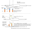
Let's assume I have a pipe with diameter A, which gets larger to diameter B - let's assume in width so the height is negligible - and then smaller to diameter A again. There is a liquid flowing through the pipe, e.g. water.
There is a small head loss in the pipe due to friction, so pOut will be smaller than pIn obviously.

Now at the part where the diameter expands from A to B, the static pressure has to increase because the kinetic energy is reduced due to the larger diameter according to the Bernoulli equation. If the friction is low, this will "overcompensate" the decrease due to friction and I can see a higher static pressure at point 2 than in point 1. Note: If the diameter had stayed the same, static pressure at point 2 would have been lower than in point 1 because of the friction.
The total pressure that consists of the static pressure and dynamic pressure has decreased nevertheless due to the friction. I hope it's correct until here.

bernoulli_branches-png.png


Now I wonder about two scenarios, if a branch is added between point 1 and point 2.
Scenario 1: The branch is flat on the ground.
According to pipe network calculation theory, the head losses in both branches should be equal and the flow will align to match that. So this means there must be a flow in the green painted branch from point 1 to 2. But, intuitively, I'd say that if I open the branch when it was in steady flow before, the fluid would rather try move from point 2 to back to point 1 through the branch as the static pressure is higher at point 2? Or is this some transient behaviour and in the end there will be a flow from left to right in both branches? In hardy cross it would not be possible to have some kind of reverse loop to my understanding. Also QIn must still equal QOut and the total pressure pIn is higher than pOut, so there could only be some internal loop.
I know if I apply Bernoulli between 1 and the upper branch and between 1 and the lower branch it must yield the same energy for both branches - but I don't know if the flow will establish at all like I expect or not to be ablw to draw the streamlines?

Scenario 2:
I modified the example 1. I have basically a similar setup, but this time the branch is added vertical and not flat.
Let's imagine the branch is not opened yet. At point 1 if I insert a vertical static pressure measuring tube (at the wall, parallel to the flow, I just imagine a thin long glass pipe), the water level would rise as high as the static pressure allows - it is not high enough to flow through the branch to point 2 (or out of the measuring tube). If I measure at point 2, the water would rise high enough to be able to flow through the branch and then down to point 1.
Here, I have the same confusion. Seen as a pipe network, I would expect the flow to be from left to right in the main pipe (lower branch) and also in the upper branch (with different velocities depending on friction and branch geometry). But, it seems it will rather flow back from 2 to 1. I could only image it flowing from 1 to 2 if I regard the total pressure which is higher in 1 than in 2.
So here I'm really confused how the flow will establish:
A) Flow from 1 to 2 - but the static pressure when opening the branch isn't high enough in 1 to pass the elevation?
B) No Flow - I can't imagine that as the static pressure in 2 is high enough to lift water as high as the horizontal part of the branch
C) Flow from 2 to 1 - Doesn't match my expectation about pipe analysis and would violate that there should be the same head loss through two parallel branches

I hope you could understand my problem and I hope to get some understanding how the flows will establish and why!
Thanks a lot in advance

PS: I know usually the kinetic pressure part is small and can often be neglected, but I want to understand it completely first.
 

Attachments

  • Bernoulli_Branches.png
    Bernoulli_Branches.png
    23.9 KB · Views: 94
Engineering news on Phys.org
  • #2
I believe that any substantial flow through the loop, as well as the geometry of the points at which the loop taps onto the main pipe, will disturb the original established flow, affecting the original pressure conditions at points 1 and 2 (and perhaps volumetric flow as well).

Those new conditions will naturally stop the looping flow, as less energy is used that way (just like in a river, the flow tends to follow the path of least resistance).

Please, see:
https://en.wikipedia.org/wiki/Principle_of_minimum_energy

https://watershapes.com/why-rivers-bend/
 
Last edited:
  • #3
If we apply the Energy Equation between ##1## and ##2## for the main branch ##A##:

$$ \frac{P_1}{\gamma} + z_1 + \frac{Q_A^2}{2 g A_1^2} = \frac{P_2}{\gamma} + z_2 + \frac{Q_A^2}{2 g A_2^2} + k_A \frac{Q_A^2}{2 g A_1^2}$$

##k_A## is a loss coefficient for the expansion.
##z_1 = z_2## on the pipe centerline

This implies that:

$$ \frac{P_2 - P_1}{\gamma} + \frac{Q_A^2}{2 g}\left( \frac{1}{A_2^2} - \frac{1}{A_1^2} + \frac{k_A}{A_1^2} \right) = 0 $$

Nothing jumping out as peculiar there that I can see, but try to poke holes in it.

Now, It seems to get goofy in the small looping branch equation: just assume a straight pipe of cross-sectional area ##A_B##:

$$ \frac{P_2 -P_1}{ \gamma} + \frac{k_B Q_B^2}{2g A_B^2} = 0 \implies $$

$$ \frac{P_2 -P_1}{ \gamma} = - \frac{k_B Q_B^2}{2g A_B^2} $$

The LHS is positive, while the RHS is negative...
 
  • #4
erobz said:
[...]
Now, It seems to get goofy in the small looping branch equation: just assume a straight pipe of cross-sectional area ##A_B##:

$$ \frac{P_2 -P_1}{ \gamma} + \frac{k_B Q_B^2}{2g A_B^2} = 0 \implies $$

$$ \frac{P_2 -P_1}{ \gamma} = - \frac{k_B Q_B^2}{2g A_B^2} $$

The LHS is positive, while the RHS is negative...
I can follow the first equation between 1 and 2 ("normal" Bernoulli without the branch). But I'm not sure how you came to the equation for the looping branch? I tried to set up the equation from 2 to the branch and from 1 to the branch, but this would give me a pressure $$ P_B $$ and not the $$ P_2 -P_1 $$ I see in your equation?
 
  • #5
axim said:
I can follow the first equation between 1 and 2 ("normal" Bernoulli without the branch). But I'm not sure how you came to the equation for the looping branch? I tried to set up the equation from 2 to the branch and from 1 to the branch, but this would give me a pressure $$ P_B $$ and not the $$ P_2 -P_1 $$ I see in your equation?
You just apply the same equation across ##1## and ##2##, but taking the head losses through branch ##B##.

$$ \frac{P_1}{\gamma} + \cancel{z_1} + \cancel{\frac{Q_B^2}{2 g A_b^2} } = \frac{P_2}{\gamma} + \cancel{z_2} + \cancel{ \frac{Q_B^2}{2 g A_b^2}} + k_B \frac{Q_B^2}{2 g A_B^2}$$

We would also have the equation for continuity, ##Q_T = Q_A + Q_B## . Those 3 eqn's are the system we would typically linearize and solve.

but I just stopped after getting something that seemed contradicting.

P.S. it not the Bernoulli. Its Conservation of Energy - "The Energy Equation" in Fluid Mechanics. It looks like Bernoulli for certain simplifying assumptions, but they are different. In "Bernoulli" flow is inviscid. If 2 pipes were connected in parallel, they both take half the flow regardless of dimensions because there is no shear.
 
Last edited:
  • #6
Actually, the system is quite simple (no linearization necessary). Just pick a total volumetric flow rate ## Q_T## and solve for either branch flow directly. I might just solve it when I get a chance and see what happens…Perhaps the pressure distribution is not as I suspect. That parallel pipe across the expansion might alter the typical behavior we expect when it isn’t there.
 
Last edited:
  • Like
Likes Lnewqban
  • #7
One thing is clear about the possible direction of flow: Matter cannot be created!

1666315583434.png


As you can see with this configuration, we have spontaneously created matter ##Q_B## in addition to the total flow ##Q_T##. So it can't flow backward like that.

"No flow" at all also seems strange because there would be a pressure gradient along the length of the branch...but no flow...

The question left to answer: Does it flow forward? Time to solve the system.
 
Last edited:
  • Like
Likes Lnewqban
  • #8
I think the answer is we can get flow, but it depends on all the parameters. At least that is what I'm being told by the solution. Shrink the downstream pipe ,or don't change size; no problem, branch ##B## gets flow. However, increase downstream pipe diameter too much for a certain set of parameters...and flow in ##B## stops.
 
Last edited:
  • #9
Here are some sample parameter sets:

Flow  - Parameter set 1.JPG


Flow - parameter set 2.JPG
 
  • Like
Likes axim
  • #10
I think the gist of it is because of the head losses through the expansion, the pipe can be larger to some extent downstream, but the pressure ##P_2## still lower than the pressure ##P_1##. You’ll notice that for any flow to occur in branch ##B## , ##P_1 >P_2##. That can’t happen in “Bernoulli’s” because there are no viscous loses.
 
  • #11
erobz said:
I think the gist of it is because of the head losses through the expansion, the pipe can be larger to some extent downstream, but the pressure ##P_2## still lower than the pressure ##P_1##. You’ll notice that for any flow to occur in branch ##B## , ##P_1 >P_2##. That can’t happen in “Bernoulli’s” because there are no viscous loses.
Thanks for the explanations and calculations so far! It already helped me about the use of the equations together with the losses.
I also get that because of the losses P2 can likely be lower that P1 because of the expansion losses. But I think it must not necessarily be always that case, correct? Depending on the chosen parameters.

So how can I imagine the flow in B stops in the case P2 would actually be higher? At the beginning, I guess it would try to push back from point 2 into the branch. But then it would somehow collide with the fluid that is already flowing at point 1 through the main branch. And here I'm not sure. Will it stop? Will it be pulled along by the main stream? Will it just cause more friction but stay like deadwater in the branch?
Probably it's difficult to answer.
 
  • #13
axim said:
I also get that because of the losses P2 can likely be lower that P1 because of the expansion losses. But I think it must not necessarily be always that case, correct? Depending on the chosen parameters.
Yeah, that's correct. It depends on how much loss there is in the expansion. You should play around with the solution for ##Q_B## for some different parameter sets. If the loss coefficient for the expansion is small (we are approaching Bernoulli's idealism of inviscid flow), then nearly any increase in pipe diameter stops the flow in branch ##B##. However, if you make the head loss is "large" across the expansion then we can increase the pipe diameter significantly before the pressure at ##P_2## becomes greater than ##P_1##. At the point where ##P_2 = P_1##, flow just stops. It can't loop back even though it feels like it could from the ##P_2>P_1## because of what has been shown in post #7.

Also in reality, you can't vary all the parameters independently like we can is this simplified representation of it. The loss coefficients ##k_A, k_b## are dependent on pipe geometry, and flow velocity.
 
  • Like
Likes Lnewqban
  • #14
Venturi is what started me start thinking in what direction the fluid in the branch will flow which lead to this post. And if I have a look at the “prohibited” drawing from post #7, I could imagine that flow only if the speed in the lower branch would increase. But then it doesn’t follow the minimum principle and I wouldn’t know how to setup the equations. I think this loop would stop itself immediately. I think we agree on that.

Hence I wonder if it will flow from lower to higher pressure to the branch (from left to right) in this case or not at all (which I understand from your point).
I wonder because the higher branch could even mean less losses from 1 to 2. But then how would it establish that branch path towards higher pressure without any diversion.
 
  • Like
Likes Lnewqban
  • #15
axim said:
I could imagine that flow only if the speed in the lower branch would increase.
The continuity in #7 is valid everywhere. We a violating some very fundamental principles of physics if we allow it. Imagining that if it was flowing faster does not fix the fact that we are spontaneously creating matter in that scenario...so I would just get that out of your head.

axim said:
I wonder because the higher branch could even mean less losses from 1 to 2. But then how would it establish that branch path towards higher pressure without any diversion.
The "Energy Equation" I used is only valid for steady state (not changing in time) solutions, so it doesn't have much to say about how the flows develop over time.

All that being said I'm certainly very far from an expert in this discipline. How "exactly" all this happens has to be massively complex...and should be left to the experts (because I will undoubtedly get it wrong). Everything I've used here is based off "averaged flow properties". As useful as those are in engineering, they run into serious trouble at describing small scale detail needed to resolve the questions you are asking.
 
Last edited:
  • #16
erobz said:
The continuity in #7 is valid everywhere. We a violating some very fundamental principles of physics if we allow it. Imagining that if it was flowing faster does not fix the fact that we are spontaneously creating matter in that scenario...so I would just get that out of your head.
I did mean it like that:
Initially, there are 10l/s flowing into the main branch (QT in the image). Then, once it reaches the branch at point 2, then 9l/s will continue towards the exit and 1l/s will go into the branch. So at that point only QT-QB can continue! Thats for sure. I don't want to violate the fundamental laws :) Once the 1l/s branch part reaches the start there will be 10l/s QT flowing into the system + 1l/s from the branch (which requires a higher speed so QT+QB can flow through the main branch). Until that time still only 9l/s (QT-QB) can reach the exit. And once the flow reaches point 2, only then 10l/s (QT) can leave the exit, while 1l/s is looping. That was my thinking, I think it was maybe confusing because I more thought it as transient until it can become steady.
But I think it would be unlikely that the fluid through the side branch would enter the main branch. Here I had something like Venturi in mind. Anyway it's only my guess what would happen.

Yes sorry for asking so detailed... I tend to get stuck with the details and extreme cases when trying to understand it completely.
 
  • Like
Likes Lnewqban
  • #17
axim said:
I did mean it like that:
Initially, there are 10l/s flowing into the main branch (QT in the image). Then, once it reaches the branch at point 2, then 9l/s will continue towards the exit and 1l/s will go into the branch. So at that point only QT-QB can continue! Thats for sure. I don't want to violate the fundamental laws :) Once the 1l/s branch part reaches the start there will be 10l/s QT flowing into the system + 1l/s from the branch (which requires a higher speed so QT+QB can flow through the main branch). Until that time still only 9l/s (QT-QB) can reach the exit. And once the flow reaches point 2, only then 10l/s (QT) can leave the exit, while 1l/s is looping. That was my thinking, I think it was maybe confusing because I more thought it as transient until it can become steady.
But I think it would be unlikely that the fluid through the side branch would enter the main branch. Here I had something like Venturi in mind. Anyway it's only my guess what would happen.

Yes sorry for asking so detailed... I tend to get stuck with the details and extreme cases when trying to understand it completely.
I think you still are confused about that scenario.

10 heads into node 1, 11 (10 from the main, 1 from the branch) comes out of node 1 (heading towards node 2). 11 enters node 2, and 11 leaves node 2 (10 in the main, and 1 in the branch). We have created 11 from 10.

If none enters from the branch at node 1 (which is what you are saying), then none can exit at the branch in node 2.
 
Last edited:
  • #18
That was my thinking, I think it was maybe confusing because I more thought it as transient until it can become steady.
So you were thinking about it being an empty pipe initially. Why should it bypass node 1 before the flow splits in that case? The pressure at node 1 would be initially higher than the pressure inside empty pipe downstream. flow would be established up node 1 before node 2.
 
  • #19
erobz said:
I think you still are confused about that scenario.

10 heads into node 1, 11 (10 from the main, 1 from the branch) comes out of node 1 (heading towards node 2). 11 enters node 2, and 11 leaves node 2 (10 in the main, and 1 in the branch). We have created 11 from 10.

If none enters from the branch at node 1 (which is what you are saying), then none can exit at the branch in node 2.
erobz said:
So you were thinking about it being an empty pipe initially. Why should it bypass node 1 before the flow splits in that case? The pressure at node 1 would be initially higher than the pressure inside empty pipe downstream. flow would be established up node 1 before node 2.
I tried to come up with a possibility if there could be a loop flow established. So I had thought experiments in mind like the side branch is first closed with gates at both sides and then suddenly opened once the main branch is steady (I could even measure the pressure difference pushing at point 2 in that case before it is opened).

The empty pipe example was just as a response to show that in my opinion I could theoretically establish a loop flow like shown in your image without creating new matter (not considering if the forces would actually do that or not).
 
  • #20
axim said:
I tried to come up with a possibility if there could be a loop flow established. So I had thought experiments in mind like the side branch is first closed with gates at both sides and then suddenly opened once the main branch is steady (I could even measure the pressure difference pushing at point 2 in that case before it is opened).

The empty pipe example was just as a response to show that in my opinion I could theoretically establish a loop flow like shown in your image without creating new matter (not considering if the forces would actually do that or not).
Well, experiment with that and let us know what happens.
 
  • #21
erobz said:
Well, experiment with that and let us know what happens.
If it was that easy I'd happily do it. Really!
I'm already thankful you helped putting up the equation.
If you agree I would conclude: As long as ##A_2<sqrt(2)## that is solvable. Once ## A_2>sqrt(2) ## the value inside ##\sqrt{(2*\beta*Q_T)^2 -4*(\beta-\frac{k_B}{A_B^2})*\beta*Q_T^2}## will become negative. I interpret this that the normal forward flow will occur until that, and afterwards it will most likely stop. But it would become very difficult to predict the exact transient behaviour as we only have a solution for the final steady state.
 
  • #22
I think at least one criterion is to keep what under the root non-negative. I didn't get what you did for the condition on ##A_2##.

$$ ( 2 \beta Q_T)^2 - 4 \left( \beta - \frac{k_B}{A_B^2} \right) \beta Q_T^2 > 0 $$
 
  • #23
erobz said:
I think at least one criterion is to keep what under the root non-negative. I didn't get what you did for the condition on ##A_2##.

$$ ( 2 \beta Q_T)^2 - 4 \left( \beta - \frac{k_B}{A_B^2} \right) \beta Q_T^2 > 0 $$
I took the second example you calculated above in post #9 and left all the other parameters constant except for the diameter ##A_2## and solved it. For other parameter combinations it would of course be other values as they influence each other. It was just valid with the other parameters unchanged.
 
  • #24
axim said:
I took the second example you calculated above in post #9 and left all the other parameters constant except for the diameter ##A_2## and solved it. For other parameter combinations it would of course be other values as they influence each other. It was just valid with the other parameters unchanged.
Just solve it in general for any parameter set (it simplifies quite dramatically).
 
Last edited:
  • #25
Just in case anybody's interested, I learned some CAD and modeled the thing in a CFD simulation :-)
Of course it's more far away from the initial theory in the post as it includes wall friction and a turbulence model, but just thought I'd put it here for completeness. Input speed is 10m/s and there is a (very small) backflow.

Mesh:
Mesh3.png


Pressure field:
Pressure.png


Velocity field:
Velocity.png
 
  • Like
Likes Lnewqban and erobz
  • #26
I don't know what to say, but I still don't think reverse flow is physically possible.
 
  • #27
Is it possible to see a finer resolution on the pressure gradient along the length of top pipe?

Another thing: Can it give the volumetric flowrate in various cross sections? I'm most interested in that just before and after the entrance of the loop.
 
  • #28
I think it gets compressed by the forum. I created some measurement points to show the pressure. Also I did a cut so we can look into the bypass from the front (rotating the model above by 90°).

Actually to me it looks a little bit like the recirculation area that is visible in a sudden pipe expansion. There it is caused by the friction and shear stress between the fluid layers (which I neglected in the original idea).

Pressure in bypass (Note: Boundary condition for outlet was 0 Pa and boundary condition for input was 10 m/s so atmospheric pressure would need to be added to the values).
BypassPressure.png


Cut and looking into the y-axis (bypass)
Speed is <1m/s. Bypass radius is 50mm and entry radius of the pipe is 100mm, so the recirculation would be less than 2.5% (less than 10% of the speed through 1/4 the area).
Y-Cut.png
 
Last edited:
  • Like
Likes Lnewqban
  • #29
And here the x-speed (flowing "into" the pipe from left to right) at the junction at the beginning. Speed is slightly higher than 10m/s because speed at the wall decreases because of friction.
X-Speed-1.png
X-Speed-2.png
 
  • Like
Likes Lnewqban
  • #30
axim said:
And here the x-speed (flowing "into" the pipe from left to right) at the junction at the beginning. Speed is slightly higher than 10m/s because speed at the wall decreases because of friction.
View attachment 316561View attachment 316562
I would like to find out what it thinks ##Q## is in those sections. Can it give us $$Q= \int v \, dA $$ for the sections you’ve highlighted?
 
  • #31
With an external tool like Paraview it should be possible, but I've never used it so far and it's rather complicated. At least I didn't manage to do it yet and would need some time to learn it first (it's not as intuitive as I hoped). If anybody is experienced enough I could upload the measurement data, though.
 
  • #32
axim said:
With an external tool like Paraview it should be possible, but I've never used it so far and it's rather complicated. At least I didn't manage to do it yet and would need some time to learn it first (it's not as intuitive as I hoped). If anybody is experienced enough I could upload the measurement data, though.
Ideally, I would stretch this system out horizontally to allow the flow to fully develop in each section too.
 

1. What is the Bernoulli equation?

The Bernoulli equation is a fundamental equation in fluid mechanics that describes the relationship between pressure, velocity, and elevation in a fluid flow. It states that the total energy of a fluid remains constant along a streamline, meaning that as the velocity of a fluid increases, its pressure decreases.

2. How is the Bernoulli equation derived?

The Bernoulli equation is derived from the principle of conservation of energy, which states that energy cannot be created or destroyed, only transferred or converted. By applying this principle to a fluid flow, we can derive the Bernoulli equation by considering the changes in kinetic, potential, and pressure energy along a streamline.

3. What is a parallel pipe branch?

A parallel pipe branch is a type of pipe configuration where two or more pipes are connected in parallel, meaning they have the same starting and ending points. This allows for the flow of a fluid to be split into multiple paths, with each path having a different flow rate and pressure.

4. How is the Bernoulli equation applied to a parallel pipe branch?

In a parallel pipe branch, the Bernoulli equation is applied separately to each pipe, as the total energy along each path must remain constant. This allows us to calculate the pressure and velocity at any point in the branch and determine how the flow is split between the different paths.

5. What are the assumptions made in the application of the Bernoulli equation to a parallel pipe branch?

The Bernoulli equation assumes that the fluid is incompressible, inviscid, and flows along a streamline. It also assumes that there is no energy loss due to friction or turbulence, and that the fluid properties remain constant throughout the flow. These assumptions may not hold true in all real-life situations, so the results obtained from the application of the Bernoulli equation should be used with caution.

Similar threads

Replies
11
Views
1K
  • Mechanical Engineering
Replies
3
Views
1K
Replies
10
Views
4K
  • Mechanical Engineering
Replies
20
Views
6K
  • Mechanical Engineering
Replies
4
Views
730
  • Mechanical Engineering
Replies
12
Views
2K
Replies
8
Views
2K
  • Mechanical Engineering
Replies
18
Views
45K
  • General Engineering
Replies
11
Views
2K
Replies
1
Views
2K
Back
Top