DC81
- 9
- 5
- TL;DR
- Weight triangulation to work out load ratings for bearings
Hi all. I'm designing a custom spare wheel carrier for my 4wd and currently seeking knowledge on which bearings to use, so I need to work out what force on the bearings will be when it's open (closed will be locked and fully supported!)
The example image is simplified for calculation. Close enough is good enough because the wheel itself would be no more than 25kg and I'm allowing 70kg to play it safe.
See below for details...

Thanks in advance folks, much appreciated!
The example image is simplified for calculation. Close enough is good enough because the wheel itself would be no more than 25kg and I'm allowing 70kg to play it safe.
See below for details...
Thanks in advance folks, much appreciated!

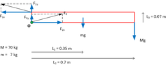


 ) as a hinge and concentrate on the torque that acts on that hinge (in particular the forces that cause the torque):