Image Theory for an Electric Dipole

14 replies · 6K views · last reply
stateissuedrx78
Messages
6
Reaction score
6
Homework Statement
A short vertical electric dipole of moment Iℓ (pointed in z direction) is placed at (a,0,a) [the xz plane, y-axis is in and out of page] and there are two infinitely long PECs, one located on the x-axis and one located at the z-axis. Use image theory to remove the two PEC planes and replace their effects with properly positioned and oriented three additional image dipoles. Calculate the vector 𝑵(𝜃,𝜙) due to the four dipoles (source + three images).
Relevant Equations
attached inline.
PREFACE: My first real post so please bear with me and my notation and layout. I tried to make it as easy on the eyes as possible...

While I am fairly confident of my process thus far, I feel I may be straying from the answer a bit towards the end.

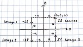
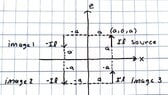
Considering the short vertical electric dipole in the +z direction, the images should be the following (I have also attached my own drawing):
source: located at (a,0,a) - oriented in the +z direction with moment Iℓ
image 1: located at (-a,0,a) - oriented in the -z direction i.e. -Iℓ moment (tangential components of E should be zero across the PEC plane)
image 2: located at (-a,0,-a) - oriented in the -z direction i.e. -Iℓ moment (normal component of E should reinforce image 1)
image 3: located at (a,0,-a) - oriented in the +z direction i.e. +Iℓ moment (normal component of E over PEC should reinforce the source)
Hand-drawn diagram on grid paper labelled original: a PEC half-plane along the z axis and a PEC half-plane along the x axis, with a source current element Il at (a,0,a) pointing up. Right side labelled images shows Il and -Il current elements at four mirrored positions across the axes.


Now, for vector N(𝜃,𝜙):
- In the textbook I am using, I found that the magnetic vector potential of an infinitesimal dipole (taken from "short" dipole as stated in the question) oriented the exact same is as given below:
Two equations for the magnetic vector potential A(r): a volume integral of J(r') times exp(-jkR)/R over V, and a line integral over z' from -l/2 to l/2 of zhat I exp(-jkR)/R, which simplifies to zhat mu I l/(4 pi r) exp(-jkr).

The textbook also states that N and A have the following relationship
Equation A = (μ / (4πr)) e^(-jkr) N, a vector potential expression written in bold A and N.

with N(𝜃,𝜙) given as
Equation N = triple integral over volume V of J e^(jk r' cos psi) dV', with the integral sign labelled V.

where r'cosΨ = r_hat*r'. where r_hat is just the r unit vector in cartesian form and r' is the source/image distance vector.
My logic is that N(𝜃,𝜙) for the source dipole would simply be Iℓ*exp(jkr_hat*r') in which the total N(𝜃,𝜙) would just be
N(𝜃,𝜙) = N(𝜃,𝜙)_source+N(𝜃,𝜙)_image1+N(𝜃,𝜙)_image2+N(𝜃,𝜙)_image3
or more explicitly as written below (sorry for the sloppy writing):
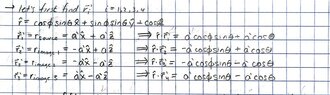
Handwritten equations on graph paper: N3 = Iℓe^(jk(a'cosφ sinθ + a'cosθ)), N1, N2 and N3 expressions with sign variations, and N(θ,φ) = N3 + N2 + N1 + N3 with a unit vector z-hat.


My next thought was to simply integrate these N's over the surface element dS=dxdz (or dx'dz' to be pedantic). I have not passed this point as the integration seems a bit brutal to tackle without some possible advise on the work so far. Thanks in advance!
 
Attachments
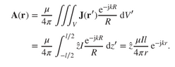
  • Two equations for the magnetic vector potential A(r): a volume integral of J(r') e^(-jkR)/R over V, and a line integral over z' from -l/2 to l/2 of z-hat I e^(-jkR)/R, which reduces to z-hat mu I l/(4 pi r) e^(-jkr).
    1741208711948.png
    3.4 KB · Views: 85
  • Handwritten derivation listing position vectors r'_i for the source and three image dipoles, with dot products r_hat · r'_i for each, using cos and sin of theta and phi.
    R VECTORS.jpg
    38.1 KB · Views: 76
  • Hand-drawn x-z diagram on grid paper of image dipoles for a PEC plane: source Il at (a,0,a), image 1 -Il at (-a,0,a), image 2 -Il at (-a,0,-a), image 3 Il at (a,0,-a), with distances labeled a and -a.
    IMAGES.jpg
    44 KB · Views: 93
  • Hand-drawn x-z plane diagram with a z-axis and x-axis crossing at the origin, showing four dipole positions at corners a and -a: source at (a,0,a) labelled Il, image 1 at top left labelled -Il, image 2 at bottom left labelled -Il, image 3 at bottom right labelled Il, with dashed distance labels a and -a.
    IMAGES.jpg
    44 KB · Views: 93
Last edited by a moderator:
stateissuedrx78 said:
My first real post so please bare bear with me
LOL, fixed that for you.
 
berkeman said:
LOL, fixed that for you.

Three photos of a large brown bear with people: an older man and woman kneeling beside a bear sitting on rocks, a shirtless man hugging a bear in snowy woods, and a man in a knit cap embracing a bear.
 
Last edited:
  • Wow
  • Like
Likes   Reactions: PhDeezNutz and berkeman
Hello and welcome to PF!

I'm not sure of the interpretation of the problem statement. Is the dipole oscillating harmonically with some angular frequency ##\omega##? So, ##k = \dfrac \omega c##?

What does PEC stand for? (Maybe "perfect electrical conductor"?)

Also, it appears to me that you are assuming ##a \ll r##.

You have an answer for ##\vec N##:

stateissuedrx78 said:
My logic is that N(𝜃,𝜙) for the source dipole would simply be Iℓ*exp(jkr_hat*r') in which the total N(𝜃,𝜙) would just be
N(𝜃,𝜙) = N(𝜃,𝜙)_source+N(𝜃,𝜙)_image1+N(𝜃,𝜙)_image2+N(𝜃,𝜙)_image3
or more explicitly as written below (sorry for the sloppy writing):
1741227582021.png

It looks to me that this is probably correct. (I wouldn't put primes on the ##a##'s.) You can simplify the sum ##N_s + N_1 + N_2 + N_3## to a fairly simple expression.

stateissuedrx78 said:
My next thought was to simply integrate these N's over the surface element dS=dxdz (or dx'dz' to be pedantic). I have not passed this point as the integration seems a bit brutal to tackle without some possible advise on the work so far. T
I don't understand why you want to integrate N over the x-z plane, or what that would even mean.
The question only asks for an expression for ##\mathbf{N}(\theta, \phi)##, which you have.
 
He's exercising his constitutional right to bare arms.

A shirtless man in a close embrace with a large brown bear, both facing left, against a blurred snowy forest background.
 
  • Haha
  • Like
Likes   Reactions: berkeman and WWGD
The image configuration you have looks right to me (I’ve done a similar problem before).

Forgive my ignorance but why are we calculating a vector potential for electric dipoles?
 
PhDeezNutz said:
The image configuration you have looks right to me (I’ve done a similar problem before).

Forgive my ignorance but why are we calculating a vector potential for electric dipoles?
I was a little confused about that also. But, if the electric dipole is oscillating, we can calculate A(r) for the radiation field.
 
TSny said:
I was a little confused about that also. But, if the electric dipole is oscillating, we can calculate A(r) for the radiation field.

That is fair. Hopefully OP will clarify.
 
TSny said:
Hello and welcome to PF!

I'm not sure of the interpretation of the problem statement. Is the dipole oscillating harmonically with some angular frequency ##\omega##? So, ##k = \dfrac \omega c##?

What does PEC stand for? (Maybe "perfect electrical conductor"?)

Also, it appears to me that you are assuming ##a \ll r##.

You have an answer for ##\vec N##:


It looks to me that this is probably correct. (I wouldn't put primes on the ##a##'s.) You can simplify the sum ##N_s + N_1 + N_2 + N_3## to a fairly simple expression.


I don't understand why you want to integrate N over the x-z plane, or what that would even mean.
The question only asks for an expression for ##\mathbf{N}(\theta, \phi)##, which you have.
- in the problem it is not mentioned if it is oscillating
- my apologies, yes PEC = perfect electrical conductor
- the end goal of the problem, which perhaps was dumb of me to leave out, is to find E and H in the far-field region and the vector N is related to the far field E via
Equation for far-field E: E ≈ −(jk/(4πr)) e^(−jkr) [θ̂(L_φ + ηN_θ) − φ̂(L_θ − ηN_φ)]

where we can ignore L in this instance.
BUT as you've brought it to question, i see now that i do not need to integrate over any surface for N because I have replaced the integral procedure with the initial logic of using the relationship between the magnetic vector potential A and the vector N (as the integration is built into A, if that makes sense??)
 
PhDeezNutz said:
That is fair. Hopefully OP will clarify.
the problem does not state if it is oscillating BUT i am using a previous result found in the same book (Theory and Computation of Electromagnetic Fields - Jian Ming Jin) for an infinitesimal electric dipole's magnetic vector potential (i am assuming this is also infinitesimal judging by the problem's word choice of "short") which I then used its relationship to N to find said vector if that makes sense. let me know if i'm not being clear enough. I appreciate everyone's input thus far!
 
With the exponential phase factor ##e^{jkr}## I’m inclined to think this system has to be oscillating and therefore radiating.

The reason that there’s no time dependence in the expression for ##\vec{E}## is because the expression for ##\vec{E}## is the average field.

It’s been awhile so I could be wrong.
 
  • Like
Likes   Reactions: stateissuedrx78
PhDeezNutz said:
With the exponential phase factor ##e^{jkr}## I’m inclined to think this system has to be oscillating and therefore radiating.

The reason that there’s no time dependence in the expression for ##\vec{E}## is because the expression for ##\vec{E}## is the average field.

It’s been awhile so I could be wrong.
I'm inclined to agree about the exponential factor. I believe it may just be an innate detail given by the problem/material at hand that just isn't explicitly said.
 
just wanted to follow up and say that i was correct in my setup. thanks everyone!
 
  • Like
Likes   Reactions: PhDeezNutz and jim mcnamara