Homework Help Overview
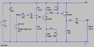
The discussion revolves around calculating the input resistance of a BJT amplifier, specifically focusing on the RS resistor in the circuit. Participants are exploring the implications of their circuit simulations and calculations, with a voltage source of 500mA mentioned, although there is some confusion regarding the units used.
Discussion Character
- Exploratory, Assumption checking, Conceptual clarification
Approaches and Questions Raised
- Participants are questioning the validity of the original poster's calculated input resistance of 95k ohms, suggesting it may be incorrect based on typical values for common emitter transistors. There are discussions about the impact of the emitter resistor and the role of AC signals in the circuit.
Discussion Status
The discussion is active, with various participants providing insights and questioning assumptions. Some have offered guidance regarding the expected input resistance values and the effects of circuit components, while others are exploring the implications of changing resistor values on output voltage.
Contextual Notes
There is mention of a specific range of expected gain for the transistor and references to simulation results, indicating that participants are working within the constraints of their circuit models and theoretical knowledge. Some participants express uncertainty about the calculations and seek clarification on the relationships between components.