Internal Forces Diagram: how to do this one?

3 replies · 3K views · last reply
ramzerimar
Messages
178
Reaction score
23
I'm wondering how should I do analysis on those problems below:
Figure 1:
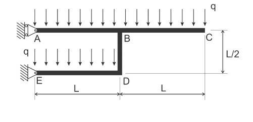
Structural diagram of a bent beam: upper member A to B to C with uniform distributed load q downward, fixed-pin support at A, vertical member B to D of length L/2, lower member E to D with uniform load q downward and pin support at E, horizontal spans labeled L.

Figure 2:
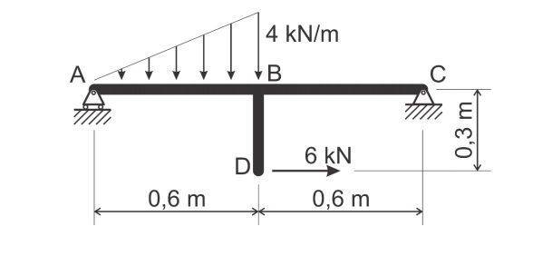
Structural diagram of a beam A to C with a pin support at A, a roller support at C, a vertical member BD hanging from B, a triangular load of 4 kN/m on AB, and a 6 kN horizontal force at D; spans 0,6 m and 0,6 m, height 0,3 m.

I mean, my professor, while doing an example very similar to Figure 2, he didn't do an imaginary cut in the region BD to find internal forces there, and the internal forces diagram that he drew only contained internal forces in sections AB and BC. I'm confused by it. When drawing internal forces diagrams, how should I handle those kinds of problems?
 
  • Like
Likes   Reactions: berkeman
After finding reactions, you should determine the internal forces and moments in all members at the joints. Then you can draw shear and moment diagrams to determine the internal forces and moments in between the joints.
 
PhanthomJay said:
After finding reactions, you should determine the internal forces and moments in all members at the joints. Then you can draw shear and moment diagrams to determine the internal forces and moments in between the joints.
Okay, so let's consider figure 2. When I draw shear and moment diagrams, I plot internal forces in function of x - where x is the distance related to the origin, let's say, point A. But the structure has joints in other directions - y direction, for instance. So, in this case, I have to draw six diagrams? Three for normal, shear and moment internal forces in the x structure, and another 3 for the joint in the y direction?
I'm confused.