magicfrog
- 41
- 4
- Homework Statement
- ToDo
- Relevant Equations
- Torque equation
Good morning everyone, I am currently working on a kinematic problem that I am having difficulty solving.
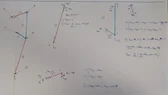
I have been asked to calculate the torque at node F based on the geometry and the force (W) applied at node G in the AG direction.
In particular, node G and node A can translate along the vertical axis and also rotate. Node F cannot translate. There are three rigid bodies, HG, AHB and FB.
I have calculated, correctly I hope, the torque at node A, considering it as a crank-connecting rod case:
T_A = W*AH*sin(alpha+phi)/cos (alpha)
From this, since AHB is a single rigid body, I can say that the rotation of point A is equal to the rotation of point H and, consequently, to the rotation of point B. But how do I link the torque at point A with the torque at point F?
I think I'm missing something, but I don't understand what.
I am attaching the kinematic diagram and my considerations.
Thank you all!
Last edited by a moderator: