Homework Help Overview
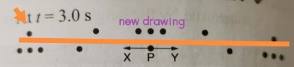
The discussion revolves around the behavior of particles in a sound wave after 1.5 periods have elapsed. Participants are examining the transition between compressions and rarefactions and interpreting a provided answer key that illustrates the positions of particles at different times.
Discussion Character
- Conceptual clarification, Problem interpretation, Assumption checking
Approaches and Questions Raised
- Participants are analyzing the relationship between compressions and rarefactions over time, questioning the accuracy of the answer key's depiction of particle positions. There is a focus on the reasoning behind the omission of certain particles in the diagrams and whether this omission affects the correctness of their own interpretations.
Discussion Status
The discussion is ongoing, with participants providing observations about the diagrams and questioning the rationale behind the representation of particle positions. Some guidance has been offered regarding the potential reasons for the omission of certain particles, but no consensus has been reached on the implications of these omissions.
Contextual Notes
Participants note that the diagrams may not include all particles due to space constraints, raising questions about the completeness of the visual representation in relation to the problem context.