kostoglotov
- 231
- 6
Currently working through a chapter on op amp circuits, fundamentals.
Came upon this practice problem in the section on inverting op amps
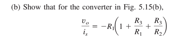
imgur link: http://i.imgur.com/2DrQLXk.png
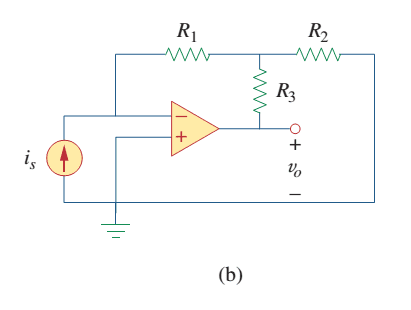
imgur link: http://i.imgur.com/7KRKzKC.png
A working of this problem is not given. I got the correct answer the second time, by working through some KCL equations on a more fundamental level, but failed the first attempt based on what is evidently an incorrect assumption. But I don't fully understand why that assumption is wrong.
Before both solutions, I converted the current source to a voltage source in series with a resistor [itex]R_s[/itex] with the equation [itex]V_s = i_s R_s[/itex].
I've labeled the node between [itex]R_1[/itex], [itex]R_2[/itex], and [itex]R_3[/itex] as [itex]v_2[/itex]. [itex]v_1[/itex] is between [itex]R_s[/itex] and the inverting input to the op amp.
My second attempt combined
[tex]\frac{-v_s}{R_1} = \frac{v_2-v_0}{R_3} + \frac{v_2}{R_2} \\ \text{with} \ \ v_2 = -i_1 R_1 \\ \text{and} \ \ i_1 = i_s[/tex]
to obtain the correct proof.
My first wrong attempt made an assumption about calculating the equivalent resistance of [itex]R_1[/itex], [itex]R_2[/itex], and [itex]R_3[/itex], that goes like this:
-- you can think of [itex]R_1[/itex], [itex]R_2[/itex], and [itex]R_3[/itex] as being a "single resistance" as their combined configuration ("lump") takes [itex]v_0[/itex] to Ground (a zero Volt node). Because the node [itex]v_1[/itex] is (theoretically/ideally) at zero volts because it is short circuited to the common analog ground because we are considering an ideal op amp, and for an ideal op amp we can think of the op amps input terminals as being a short circuit when doing voltage calculations (and as an open circuit when doing current calculations). The presence of the [itex]R_s[/itex] resistor connected to [itex]v_1[/itex] can be ignored, because it will not (ideally) change the fact that [itex]v_1[/itex] is (ideally) always 0V.
So, using this assumption, [itex]R_3[/itex] goes from [itex]v_0[/itex] into a two parallel resistors [itex]R_1[/itex], and [itex]R_2[/itex] which both (ideally) connect to the common analog ground node...soo
[tex]R_{eq} = R_3 + \frac{R_1 R_2}{R_1 + R_2}[/tex]
and
[tex]v_0 = \frac{-R_{eq}}{R_s} v_s = -R_{eq} i_s[/tex]
This of course does not work. In that it does not agree with the text or the also much more sound reasoning from just doing the KCL equations outlined initially.
What I don't understand really, is what's wrong with my reasoning in the assumption I constructed above, keeping in mind that this assumption would only work for ideal op amps (ie, [itex]v_1[/itex] is assumed as always being at 0V).
Came upon this practice problem in the section on inverting op amps
imgur link: http://i.imgur.com/2DrQLXk.png
imgur link: http://i.imgur.com/7KRKzKC.png
A working of this problem is not given. I got the correct answer the second time, by working through some KCL equations on a more fundamental level, but failed the first attempt based on what is evidently an incorrect assumption. But I don't fully understand why that assumption is wrong.
Before both solutions, I converted the current source to a voltage source in series with a resistor [itex]R_s[/itex] with the equation [itex]V_s = i_s R_s[/itex].
I've labeled the node between [itex]R_1[/itex], [itex]R_2[/itex], and [itex]R_3[/itex] as [itex]v_2[/itex]. [itex]v_1[/itex] is between [itex]R_s[/itex] and the inverting input to the op amp.
My second attempt combined
[tex]\frac{-v_s}{R_1} = \frac{v_2-v_0}{R_3} + \frac{v_2}{R_2} \\ \text{with} \ \ v_2 = -i_1 R_1 \\ \text{and} \ \ i_1 = i_s[/tex]
to obtain the correct proof.
My first wrong attempt made an assumption about calculating the equivalent resistance of [itex]R_1[/itex], [itex]R_2[/itex], and [itex]R_3[/itex], that goes like this:
-- you can think of [itex]R_1[/itex], [itex]R_2[/itex], and [itex]R_3[/itex] as being a "single resistance" as their combined configuration ("lump") takes [itex]v_0[/itex] to Ground (a zero Volt node). Because the node [itex]v_1[/itex] is (theoretically/ideally) at zero volts because it is short circuited to the common analog ground because we are considering an ideal op amp, and for an ideal op amp we can think of the op amps input terminals as being a short circuit when doing voltage calculations (and as an open circuit when doing current calculations). The presence of the [itex]R_s[/itex] resistor connected to [itex]v_1[/itex] can be ignored, because it will not (ideally) change the fact that [itex]v_1[/itex] is (ideally) always 0V.
So, using this assumption, [itex]R_3[/itex] goes from [itex]v_0[/itex] into a two parallel resistors [itex]R_1[/itex], and [itex]R_2[/itex] which both (ideally) connect to the common analog ground node...soo
[tex]R_{eq} = R_3 + \frac{R_1 R_2}{R_1 + R_2}[/tex]
and
[tex]v_0 = \frac{-R_{eq}}{R_s} v_s = -R_{eq} i_s[/tex]
This of course does not work. In that it does not agree with the text or the also much more sound reasoning from just doing the KCL equations outlined initially.
What I don't understand really, is what's wrong with my reasoning in the assumption I constructed above, keeping in mind that this assumption would only work for ideal op amps (ie, [itex]v_1[/itex] is assumed as always being at 0V).