Number of slots in collet to deform uniformly

  • Thread starter Stormer
  • Start date
  • #1
Stormer
113
22
If i have a collet that has a tapered outside to get pushed into a smaller size and a hex hole inside of it and i want the hex to uniformly shrink along the whole collet (so the walls of the hex stays parallell from one end to the other) do i need to add 12 slots or can i do it with just 6 slots like shown in the drawings?

Collett 1.JPG
Collet 2.JPG

If it can be done with only 6 slots that is preferable because i don't end up with slots in the flats of the hex.
 
Engineering news on Phys.org
  • #2
Stormer said:
If it can be done with only 6 slots that is preferable because i don't end up with slots in the flats of the hex.
For a correctly sized hexagonal collet, 6 slots should be sufficient, indeed preferable, since the corners of the hexagon are critical to the alignment.

The best hexagonal collet might have slots in the flat faces, so that the alignment of all six corners was maintained.

If the size of the hexagon was different to the collet, then more slots will be required to allow for a greater change in the dimension. That is why a set of round collets have more slots, to allow for intermediate diameters with a mismatched surface radius.

A three jaw chuck can drive the rotation of a drill, and handle the axial forces. It takes a six jaw chuck or collet to handle side forces in a milling machine.
 
  • Informative
Likes hutchphd
  • #3
Baluncore said:
If the size of the hexagon was different to the collet, then more slots will be required to allow for a greater change in the dimension.
I want to lap/grind the collet after hardening to get a good surface finish and get rid of any distortion from heat treatment, and that plus clamping on a hex that might vary slightly in size and it will slide trough the collet kind of like in a swiss lathe is why i want the flats to remain parallell trough the clamping range. So i get max surface area of the collet contacting the hex it is clamping on. It will be a very minimal clamping range required of maybe 0.1 to 0.2 mm max for a 8 mm hex.
 
  • #4
Stormer said:
So i get max surface area of the collet contacting the hex it is clamping on.
Two flat faces in contact, do not prevent rotation of one face on the other. When turning a hexagonal nut or prism with a spanner, or gripping it with a collet, there is no useful pressure applied to the centre of the face, as it will slip. The corners are more important in that they align in two planes with the hexagon, so they control direction. That is why I would slit six faces at one end, rather than six corners. If you slit three corners, you will have only three pairs of fixed faces, not six.
 
  • Informative
Likes hutchphd
  • #5
Baluncore said:
That is why I would slit six faces at one end, rather than six corners.
You mean 3 at each end right? Only slitting one end will make the hex pinch only that end, not the whole length of the collet.
 
  • #6
Stormer said:
You mean 3 at each end right?
You must slit both ends, but the shape of the collet will decide the closure at both ends.
If you slit 3 faces at one end, you can slit the other 3 faces at the other.
If you slit 6 faces at one end, you can slit the 6 corners at the other.

The old geared hand drills, and the brace and bit, both had 2 jaws, but with a 'v' profile in each, to grip the drill shank. That was sufficient for drilling. The more 'v' jaws you have, the better the collet will handle side forces. You can have 3 'v' jaws at each end, or 6 'v' jaws at the business end, with six flats at the other. You must find a compromise based on your requirements.

If you have access to wire EDM, or a thin abrasive disc, you could slit the collet after it is hardened, polished and finished. Nitriding causes less distortion than case-hardening.
 
  • #7
Baluncore said:
If you have access to wire EDM, or a thin abrasive disc, you could slit the collet after it is hardened, polished and finished
If you want to finish the ID before slitting it you would have to make an expanding lapping / grinding arbor, while if you slit it first you can use a fixed size lapping hex and use the collet to tighten it as you grind away material. So slitting it before finishing the ID seams like the simplest solution.

I don't have acess to wire EDM, but thin diamond coated abrasive discs are cheap and easy to get to make the slots after hardning.

So my thinking is to start with a soft silver steel round stock and then:
  1. drill and broach the ID hex
  2. rough machine the OD taper
  3. harden and temper
  4. grind the OD taper to finish size
  5. cut the slots in the collet
  6. lap the ID hex using the collet to tighten as you progress.
 
Last edited:
  • #8
Baluncore said:
For a correctly sized hexagonal collet, 6 slots should be sufficient, indeed preferable, since the corners of the hexagon are critical to the alignment.
This is what I find on my ER25 collets but aren't they essentially for circular tool shafts? I just wonder whether a three jaw collet would be stronger as there is a 120 degree slot for each vertex of the hex. It may be that the range of tool sizes may be less for the three jaw arrangement but is it a trade-off? Thinking in terms of spanners / wrenches a hex spanner works better (stronger and less deformation as half of the vertices on a normal spanner are not used) - it's just not convenient to get the working angle right.
 
  • #9
sophiecentaur said:
I just wonder whether a three jaw collet would be stronger as there is a 120 degree slot for each vertex of the hex.
The problem is that you have to close the slots in order for the collet to not be 3 separate pieces. So if you close the 3 slots in one end, and keep them open in the other the collet will just be able to clamp on the end with the open slots, and with a simple taper along the whole OD of the body it will not be able to clamp at all because the end with the closed slots will resist compressing and stop the collet from going further down the taper.

On a 5C collet you can get away with only open slots on one end because the taper is only on the open slot end of the collet, while the rest of the collet OD is straight walled. But this will mean that the collet will only clamp at the very end of the collet, not the whole way down the collet like a ER collet does. That is also why ER collets have a much bigger clamping range than 5C style collets.

On some CNC machine collets for automatic clamping they do a kind of hybrid between the ER style and the 5C style where they only open the slots at one end, and can clamp it by pulling from the rear like a 5C collet, but they move the taper a little furter back compared to the 5C, and have a long flexure section that allow the collet to flex into a parallel clamping situation like the ER collet can. With this design you can get away with 3 slots for a hex, but it is a much more complex design and it has a limited length clamping area because the end will be unsupported because it has no taper.
swiss-tf37-hex-collet-alt1.jpg
 
Last edited:
  • #10
A collet can be closed by pulling it, with a draw-bar, into a machine taper. But then there cannot be slots cut in the threaded draw bar end of the collet.

A collet that is slotted at both ends, must be en-closed by a cover nut in a tapered chuck, like the ER series collet chucks. The collet chuck can then be held in place with a draw-bar.

Stormer said:
On a 5C collet you can get away with only open slots on one end because the taper is only on the open slot end of the collet, while the rest of the collet OD is straight walled. But this will mean that the collet will only clamp at the very end of the collet, not the whole way down the collet like a ER collet does.
You are ignoring the radial flexibility of the thinner-walled slotted shank, between the back of the collet grip and the draw bar thread.
 
  • #11
Baluncore said:
You are ignoring the radial flexibility of the thinner-walled slotted shank, between the back of the collet grip and the draw bar thread.
That is what i was writing about the third style of collet. But this flexing to become parallell does require the part that is being held is supporting the ID the whole length of the gripping section of the collet. While a ER style collet will remain mostly parallell even if it is only supported by the part being clamped for a little part of the clamping length because the whole OD of the collet is supported by the tapers and it flexes equally at both ends because of open slots at both ends.

I have illustrated the problem here with a 5C style collet that is clamping a ball further in from the tapered end:
Collet 3.JPG

As you can see the ID of the clamping section does not stay parallell because it is not supported by the part it is clamping. This will result in the ball in this example not being able to slide trough the collet if it is pushed (like in a swiss lathe) because the end of the collet is smaller than the ball it is clamping because the clamping part of the collet is being flexed out of parallell.
 
Last edited:
  • #12
Stormer said:
So if you close the 3 slots in one end, and keep them open in the other the collet will just be able to clamp on the end with the open slots
Intermediate slots at the back end enable better fit all the way along the tool but the range of adjustability will always be limited and, as @Baluncore says, this always will require a holder which compresses the front of the collet as well as just pulling the back end into a rear taper.

After reading what's been written here, it's a wonder that a regular Jacob's chuck works at all.
 
  • #13
sophiecentaur said:
After reading what's been written here, it's a wonder that a regular Jacob's chuck works at all.
The Jacob's chuck is simply a three part collet that is adjusted by a threaded nut. The three tapered jaws remain parallel. There is a mismatch in the radius of curvature of the outside of the jaws as they move axially along the conical taper with a changing radius of curvature. The way that cone to jaw contact is arranged, makes a difference in the specifications of Jacob's chucks from different manufacturers.

The very limited clamping range, of for example ER series collets, avoids such a large and significant change in outer radius, and permits the thin slots to be cut from both ends, that restrict the clamping range while remaining elastic, avoiding yield of the collet material.
 
  • #14
Baluncore said:
The Jacob's chuck is simply a three part collet that is adjusted by a threaded nut. The three tapered jaws remain parallel. There is a mismatch in the radius of curvature of the outside of the jaws as they move axially along the conical taper with a changing radius of curvature. The way that cone to jaw contact is arranged, makes a difference in the specifications of Jacob's chucks from different manufacturers.

The very limited clamping range, of for example ER series collets, avoids such a large and significant change in outer radius, and permits the thin slots to be cut from both ends, that restrict the clamping range while remaining elastic, avoiding yield of the collet material.
From what you are saying, you also seem to imply that it actually is surprising that the Jacobs chuck is used to often. But. to be fair, a JC is only of serious use when the load is axial - as in regular drills. I have heard of several instances where someone has decided to fit a milling table to their drill press and had a disaster when they tried to do milling on it.
But it's always a problem when you want a collet to work over a wide range of tool sizes. I fairly randomly bought myself an ER system and I get by on a fairly limited set of tools and collets. Spending just a few quid on a new size doesn't break the bank.
 
  • #15
sophiecentaur said:
as @Baluncore says, this always will require a holder which compresses the front of the collet as well as just pulling the back end into a rear taper.
No it does not. A continuous OD taper along the whole clamping length works just fine to uniformly compress the collet. As demonstrated by morse taper collets. And it works even better like the design in the opening post shows pushing it into the taper rather than pulling it because then the clamping length can be the whole length of the collet because you don't need a long thin flexure section at the back to allow it to go from the treaded end to the clamping section of the collet.

My application is that a short hex section should slide back and froth inside of a long collet with uniform clamping pressure the whole way and no binding. So there will be a lot of unsupported length of the ID, and that is why i want the collet ID to stay parallell even if it is only supported for a short section by the hex it is pushing against. And that is why i need the collet to have a long continuous OD taper so the ID walls stay parallell.
 
  • #16
You need is not look at Surface Finish. You need to control of Form Error
We need to control Form Error caused by the production process. This is critical with respect to hydraulic seals, bearing load surfaces, mating surfaces of high accuracy, precision metal parts. Every ID and OD made by a machine tool will deviate from perfect roundness to some degree. You can expect lobing errors from 2 to 9 or more around the circumference of a production part. The spacing and number of lobes can be odd or even, regular or irregular and the height will vary as well.
Causes of Form Error - All surfaces of a typical OD are generated with reference to fixed points, axes or lines of contact in the machine tool, be it centerless grinding, lathe centers, steady rests, regulating wheels, tool edges, grinding wheel surfaces. These points of contact are constantly changing. Tool holders flex, there is imperfect rotation, erratic cutting dynamics, tooling wear, lubrication, rotational imbalance and wear, improper machine tool geometry, all contribute to error. Tool holders and holding fixtures slip, belts wear, drive rollers misalign, chucks distort, localized heating, excessive feed rates, and warped out of round stock all add to the mix.
Finally, it seems that the most common machine tool used, “centerless” Machine tools were designed to make out of round parts! They contact the production part at three points and almost always generate a 3,5 or 7 lobe part.

It should be noted that one could not effectively measure SIZE of high precision parts without knowing the Shape …i.e. effects of form deviation due to lobing error generated during the machining process. Knowing Form Error is mandatory, when assembling tight tolerance precision parts. The time-honored mistake of “ tightening up the Tolerance” will not cure the problem. Control of Form Error will reduce scrap, reduce rework, eliminate waste and save time and money.

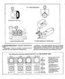
Short answer - the more slots in a collet will mean less deformation during the machining process and learn how to measure form error correctly. Micrometers and V blocks won't do it. Long answer is understand form error and this requires your additional work.


Attachments

  • form error.jpg
    form error.jpg
    51.8 KB · Views: 45
Last edited:
  • Informative
Likes sophiecentaur
  • #17
Stormer said:
No it does not.
Beg to differ. My ER25 collets are all 'compressed' axially into the tapered holder by a collar. There is a reverse taper for the first few mm, in the collar. The collet is not pulled into the holder.
Easy misunderstanding if you don't use ER's
1695805999438.png
 
  • #18
sophiecentaur said:
Beg to differ. My ER25 collets are all 'compressed' axially into the tapered holder by a collar. There is a reverse taper for the first few mm, in the collar. The collet is not pulled into the holder.
Easy misunderstanding if you don't use ER's
View attachment 332653
The reason for the front taper is because of the collar so you are able to pull the collet out from the front because the ER collets has a semi locking taper that needs to be pullet out with force to release. If it had been pushed in from the front, and pushed out from the back it would not need the front taper but could just have a continuous taper like in the opening post, or like a Morse Taper collet
0223-0312-A.jpg
 
  • #19
Stormer said:
The reason for the front taper is because of the collar so you are able to pull the collet out from the front
Could you explain that please? How does the front taper allow the collet to be 'pulled out'? The slope is the wrong way for that. The circular groove would allow the collet to be removed from the holder, once the nut is removed.
I am bit confused about this. Is the taper just to make the nut stronger?
 
  • #20
sophiecentaur said:
Could you explain that please? How does the front taper allow the collet to be 'pulled out'? The slope is the wrong way for that. The circular groove would allow the collet to be removed from the holder, once the nut is removed.
I am bit confused about this. Is the taper just to make the nut stronger?
The circular grove is what i mean when i say "collar" The front taper is there to give the collet support in front of the "circular groove" so you can for example clamp tools that is not sticking verry far into the collet.

As i said if you push the collet from the rear to release it there is no reason for "the circular groove" or the front taper. They are only there so that you can both clamp and release the collet from the front with a collet nut.

But this stuff is way off topic. The geometry's of different kinds of collets has noting to do with the question i asked about the minimum number of slots to compress a collet uniformly around a hex.
 
  • Like
Likes sophiecentaur
  • #21
To make a collet, like an ER with an 8°, 1 in 7.115 taper I would:
1. Bore and internally grind, a female conical taper socket.
2. Turn and grind a conical plug to fit.
3. Mount the plug in the socket.
4. Drill and bore the plug to the cylindrical size required.
5. Remove the plug, and cut slots to allow an expansion, or clamping contraction.
Now, if my workpiece fitted exactly in the bore, all surfaces would be in contact. But ER collet sets come with multiples of 1 mm bores.

If my workpiece was under-size by 1 mm, (I exaggerate slightly), the plug would need to be pushed into the socket by an extra 7.115 mm. If the workpiece was over-size by 1 mm, the plug would fall 7.115 short in the socket.

Because the apex of the identical conical tapers can differ in axial position by 7.115 mm, the radius of curvature of the conical surfaces will not match. One will be able to rock on the contact line with the other, or will contact only along two lines. The curved surfaces may be deformed by the increased pressure along the line contacts. That analysis also holds for the workpiece held in the cylindrical bore.

Will more slots cut in the collet reduce the rocking errors, but make the collet more flexible and so less accurate?
 
  • #22
Baluncore said:
Will more slots cut in the collet reduce the rocking errors, but make the collet more flexible and so less accurate?
This looks like a possibility. The total of gaps between each finger of a collet will add up as the number is increased. That would reduce the possible range of tool size.
 
  • #23
Stormer said:
The front taper is there to give the collet support in front of the "circular groove" so you can for example clamp tools that is not sticking verry far into the collet.
Exactly. It gives a longer overall length of finger.
 

Similar threads

Replies
2
Views
603
  • Mechanical Engineering
Replies
31
Views
2K
  • Engineering and Comp Sci Homework Help
Replies
6
Views
5K
  • Engineering and Comp Sci Homework Help
Replies
1
Views
1K
Replies
0
Views
101
  • Sci-Fi Writing and World Building
Replies
9
Views
2K
Replies
7
Views
1K
Replies
10
Views
2K
  • Electromagnetism
Replies
1
Views
1K
Replies
25
Views
2K
Back
Top