PhysicsTest
- 260
- 27
- TL;DR
- Phase current sensing and the phase delay
This is the phase current sensing circuit
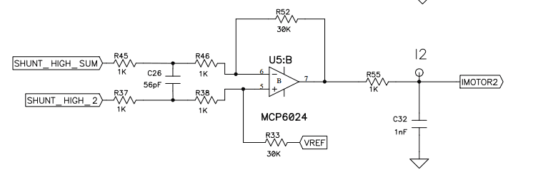
Here the phase currents are converted to voltages by passing through shunt resistor and fed to the opamp. Two questions i have
a. Can I analyze the R45, R37, C26 as one filter circuit and the remaining as other circuit for gain?
b. The phase currents are converted into voltages after passing through shunt resistor and are available at the output of the opamp. Does the capacitor C26 add any phase delay?
Here the phase currents are converted to voltages by passing through shunt resistor and fed to the opamp. Two questions i have
a. Can I analyze the R45, R37, C26 as one filter circuit and the remaining as other circuit for gain?
b. The phase currents are converted into voltages after passing through shunt resistor and are available at the output of the opamp. Does the capacitor C26 add any phase delay?