Questions about bjt amplifier circuit

Join the discussion
Ask a follow-up here, or get your own question answered by working scientists, mathematicians and engineers — people, not an autocomplete.
Real named experts · corrections over time · the nuance an AI answer skips
7 replies · 5K views
green-fresh
Messages
14
Reaction score
0
hi all i have some questions about a commen emmiter bjt amplifier circuit .
if i had this circuit :
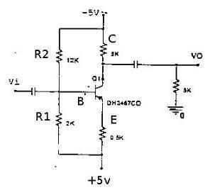
attachment.php?attachmentid=36036&stc=1&d=1306749925.jpg


and i want to find the ripple of voltage in outout :
i will use this equation :
[tex]V_{O(p-p)}=2I_{CQ} (R_L || R_C)[/tex]

but why i put[tex]R_L || R_C[/tex] not [tex]R_L || R_C + R_E[/tex] or how i conclude that this is the equivalent resistance at output .
is this connected with thevnin equivalent circuit at output if so !how.
and is it right that i can here in this problem put one power source (10v) without any change on answers.
thanks .

p.s: this isn't a homwork.
 

Attachments

  • pic91.jpg
    pic91.jpg
    6.8 KB · Views: 1,293
Engineering news on Phys.org
ummm

that's not what I would consider a common emitter configuration.
common emitter ( base or collector) usually infers that that "leg" E, B or C is connected to 0V, either directly or via a resistor
Your cct isn't showing either of those 2 usual configurations, rather its working off a split supply + and - 5V

be interesting to see what more learned people say :)

Dave
 
The input is the base, the output is the collector. What else could it be other than a common emitter? RL is in parallel with RC as far as and AC signal is concerned.
 
davenn said:
ummm

that's not what I would consider a common emitter configuration.
common emitter ( base or collector) usually infers that that "leg" E, B or C is connected to 0V, either directly or via a resistor
Your cct isn't showing either of those 2 usual configurations, rather its working off a split supply + and - 5V

be interesting to see what more learned people say :)

Dave

They call it common emitter because the emitter is common to both the input and output, that doesn't imply that the emitter must sit at ground.
 
  • Like
Likes   Reactions: cabraham
green-fresh said:
and i want to find the ripple of voltage in outout :

By that do you mean the small signal(AC) component of the output?

but why i put
RL||RC
not
RL||RC+RE
or how i conclude that this is the equivalent resistance at output .

You should really draw the small signal model of this amplifier and show us what you come up with, if you're doing that wrong this may the source of your confusion. On the other hand, if you're not drawing the small signal model that may be the source of your confusion.

After doing so it should be obvious that,

[tex]R_{out} = R_{c}//R_{L}[/tex]
 
jegues said:
They call it common emitter because the emitter is common to both the input and output, that doesn't imply that the emitter must sit at ground.

ahhhhh ok, appreciate that, we live and learn. I guess my misunderstanding comes from always seeing common E, B or C when one of them is tied to GND (0V) in either of the 2 manners I commented on.
The emitter tied to a V rail threw me a curve ball

thanks jegues and averagesupernova

Dave
 
jegues said:
By that do you mean the small signal(AC) component of the output?
yes this is what i mean.
jegues said:
You should really draw the small signal model of this amplifier and show us what you come up with, if you're doing that wrong this may the source of your confusion. On the other hand, if you're not drawing the small signal model that may be the source of your confusion.

After doing so it should be obvious that,

[tex]R_{out} = R_{c}//R_{L}[/tex]

yea exactly this is what i must do and like what i asked:
green-fresh said:
is this connected with thevnin equivalent circuit at output
i find after googling about small signal model that i must at AC consider every capacitor as "short circuit" and also the power source so[tex]R_L[/tex] and[tex]R_C[/tex] have two commen point (one at C and one at GRD)so

[tex]R_{out} = R_{c}//R_{L}[/tex].
confusion solved thanks very much:
davenn,jegues,Averagesupernova
 
green-fresh said:
and i want to find the ripple of voltage in outout :
i will use this equation :
[tex]V_{O(p-p)}=2I_{CQ} (R_L || R_C)[/tex]

BTW. That is neither the output ripple nor is it the small signal output. It is an approximation to the maximum possible peak to peak output voltage assuming a mid point bias. That comes from a large signal analysis. Start by trying to understand the small signal analysis and basic bias point calculations first.