Questions about Using My Multimeter

19 replies · 4K views · last reply
Alex Hughes
Messages
54
Reaction score
13
So I'm fairly new to electronics. I took physics 2 in college and thought I'd give the hobby a try. I started with a very basic circuit. Just a power supply connected to a light-bulb. However, as simple as it was, I had several questions when taking the reading of my circuit with a multi-meter.

Question 1:
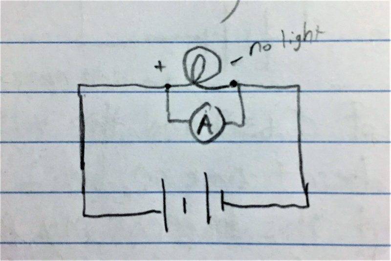
Hand-drawn circuit schematic: a battery on the bottom wire, with a lamp drawn at the top and labelled "no light", and an ammeter drawn in parallel with the lamp, connected across the lamp's two terminals.

When I hook up my multi-meter as shown (I'm aware this isn't a good way to do it I'm just experimenting), I get a reading of 0.64A when I set it to measure current but the light-bulb goes out. Now I'm aware this is probably because the circuit is skipping over my light-bulb and just going through my multi-meter, but aren't the terminals to the light-bulb still in contact with the wire? Why would the current choose to go through the path of the meter and not through the light-bulb?

Question 2:
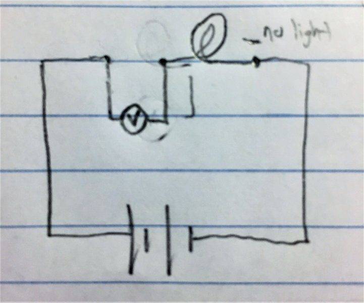
Hand-drawn circuit with two cells in series, a bulb marked no light, and a meter placed in parallel with the bulb branch, bypassing it.

Now this time, I set my multi-meter to read voltage and it gave me a reading of around 3V which is what my power supply is set at. However, the light-bulb does not come on. Now I don't see how there is a voltage drop in the areas I connected my meter to. Does the meter somehow drop the voltage down when the current goes into it and that's why my light-bulb doesn't come on, yet I get a voltage reading? I'm so confused.

Question 3: (Last Question)
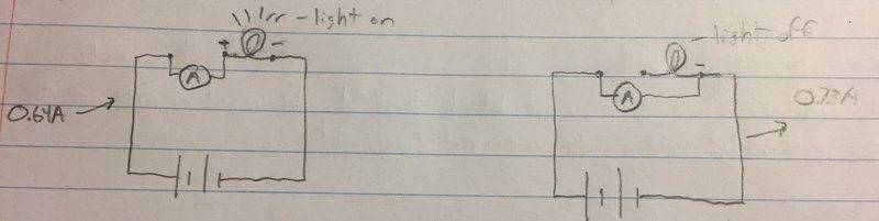
Two handwritten circuit schematics on lined paper, each with a battery, an ammeter marked A and a light bulb. Left: bulb labelled light on, current 0.61A. Right: bulb labelled light off, current 0.73A.

Ok, so in this circuit I hooked up my ammeter two different ways. The first reading gave me a current of 0.64A at a constant voltage from my power supply of around 3V. The second circuit also gave me a current reading but at 0.74A. The second way also caused my power supply to switch from C.V mode to C.C mode instantly. I understand that it probably reads more amps because the light-bulb is not drawing power from it, but why is my power supply making a slight hissing noise and switching to CC mode when I do this?

I think a lot of this would make more sense if somebody could describe to me exactly how a multi-meter works, and how it changes how it reads things when it goes from measuring voltage, to current, to resistance. Sorry, I'm a perfectionist and these aren't making much sense to me. Would love some detailed feedback. Thanks!
 
Attachments
  • Hand-drawn circuit schematic: a battery on the bottom wire, with a lamp drawn at the top and labelled "no light", and an ammeter drawn in parallel with the lamp, connected across the lamp's two terminals.
    Project1_pic2.jpg
    39.7 KB · Views: 776
  • Hand-drawn circuit with two cells in series, a bulb marked no light, and a meter placed in parallel with the bulb branch, bypassing it.
    Project1_pic1.jpg
    35.2 KB · Views: 852
  • Two handwritten circuit schematics on lined paper, each with a battery, an ammeter marked A and a light bulb. Left: bulb labelled light on, current 0.61A. Right: bulb labelled light off, current 0.73A.
    Project1_pic3.jpg
    17 KB · Views: 744
Last edited by a moderator:
Alex Hughes said:
When I hook up my multi-meter as shown (I'm aware this isn't a good way to do it I'm just experimenting), I get a reading of 0.64A when I set it to measure current but the light-bulb goes out. Now I'm aware this is probably because the circuit is skipping over my light-bulb and just going through my multi-meter, but aren't the terminals to the light-bulb still in contact with the wire? Why would the current choose to go through the path of the meter and not through the light-bulb?
Alex Hughes said:
Now this time, I set my multi-meter to read voltage and it gave me a reading of around 3V which is what my power supply is set at. However, the light-bulb does not come on. Now I don't see how there is a voltage drop in the areas I connected my meter to. Does the meter somehow drop the voltage down when the current goes into it and that's why my light-bulb doesn't come on, yet I get a voltage reading? I'm so confused.
Ok this is weird.
Alex Hughes said:
Ok, so in this circuit I hooked up my ammeter two different ways. The first reading gave me a current of 0.64A at a constant voltage from my power supply of around 3V. The second circuit also gave me a current reading but at 0.74A. The second way also caused my power supply to switch from C.V mode to C.C mode instantly. I understand that it probably reads more amps because the light-bulb is not drawing power from it, but why is my power supply making a slight hissing noise and switching to CC mode when I do this?
Oh, this is very dangerous. You should not be plugging an ammeter in series in a circuit. The ammeter has (or should, and in this case obviously does) very little resistance and the current will short circuit everything in the circuit. Your power supply, gone, ammeter, gone, wires, on fire.

I seriously don't know what is happening with your multimeter. It is obviously malfunctioning. Furthermore, the ammeter doesn't even have a fuse in case you plug it in series. Please show us what ammeter you are using and what setting it is on.

Also, please do not continue experimenting without consulting with us or at least revising a little bit more about electricity.
 
What you need to understand is that an ideal ammeter shorts its two terminals, then displays how much current flows through that short.
Ideal voltmeter is an open circuit between its terminals, and displays how much voltage is across those open terminals.

Thus, you can't force current through an ideal voltmeter, and you can't force voltage across an ideal ammeter
 
  • Like
Likes   Reactions: Asymptotic
lekh2003 said:
Ok this is weird.

Nothing weird here, everything works as expected.

During measurements ammeter should be connected in series with the load, otherwise (if connected in parallel) it will "steal" the current, as it has a very low internal resistance. Voltmeter should be connected parallel to the load, as it has a very high internal resistance and - if put in series - will effectively block the current. Details can be easily explained using Kirchoffs laws and should be a part of every discussion of how to correctly use meters. Khan academy has a video on the subject (although he doesn't go into math).
 
  • Like
Likes   Reactions: Asymptotic, jim hardy and Alex Hughes
Borek said:
Nothing weird here, everything works as expected.

During measurements ammeter should be connected in series with the load, otherwise (if connected in parallel) it will "steal" the current, as it has a very low internal resistance. Voltmeter should be connected parallel to the load, as it has a very high internal resistance and - if put in series - will effectively block the current. Details can be easily explained using Kirchoffs laws and should be a part of every discussion of how to correctly use meters. Khan academy has a video on the subject (although he doesn't go into math).
Ahhh, yes. I have forgotten my electricity just like the OP. I recommend that the OP follow Borek's post instead of mine.
 
  • Like
Likes   Reactions: ISamson
Borek said:
Nothing weird here, everything works as expected.

During measurements ammeter should be connected in series with the load, otherwise (if connected in parallel) it will "steal" the current, as it has a very low internal resistance. Voltmeter should be connected parallel to the load, as it has a very high internal resistance and - if put in series - will effectively block the current. Details can be easily explained using Kirchoffs laws and should be a part of every discussion of how to correctly use meters. Khan academy has a video on the subject (although he doesn't go into math).
That makes so much sense, thank you very much. I'm still curious though on my third question onto why it switches to CC. Is this because I'm increasing the current since there isn't a load in my circuit other than the meter and it passes the max setting I allowed for my power supply? If this was the case, If I set the max allowed current of my power supply all the way up, would it possibly cause a short circuit and blow a fuse?
 
Question 3: In the right-hand diagram, the ammeter is shorting out the power supply leads because it has a very low resistance. The power supply is limiting the current to whatever you set it to. The power supply current setting is a maximum level - in fact, the way to set this is to short the leads and turn the knob until the current is at your desired maximum. The supply will then limit any current to this level, even in the event of a dead short, by dropping the voltage. You should see this on the readouts.
 
The ammeter measures current by being placed in series in the circuit. It passes current through a very low, but known resistance, say 0.01 ohm. It measures the voltage drop across this resistance (called a shunt). This means, because R=V/I, that the meter will measure 0.01 volts per amp flowing through the shunt. It converts this voltage reading to amps and displays the reading.

Because the ammeter is a shunt, or short, you should never place it directly across a voltage source, especially a non-regulated one. A car battery would make short work of your meter, and a mains socket is potentially lethal. Never leave the meter set in amps mode for this reason - get into good habits early and set it to volts, pulling the lead out of the amps socket, before you put it away.

The voltmeter measures by passing a very small current through a high resistance. If you place it in series with the circuit, it will block almost all the current and just measure the source voltage.

May I gently suggest you stick to your regulated power supply and simple bulbs till you have a better understanding of meters, supplies, and electricity in general? Questions 1 and 2 could be placed in a textbook as examples of exactly how NOT to use a meter. Experimenting and questioning are good things, though. I wish you all the best, and stay safe.
 
  • Like
Likes   Reactions: Alex Hughes
Guineafowl said:
The ammeter measures current by being placed in series in the circuit. It passes current through a very low, but known resistance, say 0.01 ohm. It measures the voltage drop across this resistance (called a shunt). This means, because R=V/I, that the meter will measure 0.01 volts per amp flowing through the shunt. It converts this voltage reading to amps and displays the reading.

Because the ammeter is a shunt, or short, you should never place it directly across a voltage source, especially a non-regulated one. A car battery would make short work of your meter, and a mains socket is potentially lethal. Never leave the meter set in amps mode for this reason - get into good habits early and set it to volts, pulling the lead out of the amps socket, before you put it away.

The voltmeter measures by passing a very small current through a high resistance. If you place it in series with the circuit, it will block almost all the current and just measure the source voltage.

May I gently suggest you stick to your regulated power supply and simple bulbs till you have a better understanding of meters, supplies, and electricity in general? Questions 1 and 2 could be placed in a textbook as examples of exactly how NOT to use a meter. Experimenting and questioning are good things, though. I wish you all the best, and stay safe.
Thank you for your help, and I was aware that what I was doing was not what I was supposed to do, but figured since the voltage was low enough I wouldn't cause any harm. I was just curious on what the meter would say. I understand that I have to be safe and will only be sticking to low voltage circuits for now.
 
  • Like
Likes   Reactions: jim hardy
This is how we learn. Keep up the good work.
 
  • Like
Likes   Reactions: Tom.G and jrmichler
Alex Hughes said:
I was aware that what I was doing was not what I was supposed to do, but figured since the voltage was low enough I wouldn't cause any harm. I was just curious on what the meter would say.

Worst case is that you would have let the magic smoke out of your multimeter, in which case you would have performed a smoke test. Google the terms, all EE's know them.
 
Tip: When you finish with a meter always leave it on a high volt setting. If you leave it on a high current setting then next time you go to use it (perhaps to check the voltage of a car battery!) you might forget to check and...
 
CWatters said:
Tip: When you finish with a meter always leave it on a high volt setting. If you leave it on a high current setting then next time you go to use it (perhaps to check the voltage of a car battery!) you might forget to check and...
NO, turn it to the off position ... else next time you go to use it, the internal battery is likely to be flatD
 
  • Like
Likes   Reactions: sophiecentaur and lekh2003
davenn said:
NO, turn it to the off position ... else next time you go to use it, the internal battery is likely to be flat

Actually - do both :wink: I have an older multimeter with a separate on/off switch and dial for function selecting.

But thing that I really, really have to remember is to move the red cable from the A to V socket, and never to leave them in COM/A combination.
 
  • Like
Likes   Reactions: sophiecentaur, CWatters and davenn
Borek said:
Actually - do both :wink: I have an older multimeter with a separate on/off switch and dial for function selecting.
Picture? I have only ever seen the new age easy to use ones. What does vintage feel like:cool:?
 
  • Like
Likes   Reactions: davenn
It is actually not THAT old, I got it second hand somewhere in nineties but I don't think it was older than 2-3 years at the time.

(Image stolen, no time for taking pictures ATM)
 
Attachments
  • Yellow handheld digital multimeter, Metex M-3610, with an LCD display at top, a rotary dial with settings for OHM, hFE, DCV, ACV, DCA and ACA, and four input jacks labelled 20A, A, COM and V/Ω.
    IMG_1558.jpg
    29.4 KB · Views: 614
all my digital ones (4 or 5 different models) all have an off position on the rotary switch

eg my Fluke meters. My Fluke 87 is more than 25 yrs old
this is the model ( but not my well worn one haha)

Fluke 87 V True RMS multimeter, yellow and grey, showing 0.000 on the display with the rotary dial set to the OFF position and red test lead jacks below.
lekh2003 said:
Picture? I have only ever seen the new age easy to use ones. What does vintage feel like:cool:?

many of the modern ones have a separate power switch

modern one with a separate power switch ...
Clarke CDM 45 digital multimeter with yellow and black rubber casing, LCD display showing 139, rotary dial selector, and red and black test leads attached.


Front view of a green and black MASTECH MS8265 digital multimeter with an LCD display, HOLD, LIGHT and ON/OFF buttons, and a rotary function dial with input jacks labelled COM, VΩHz and mA/μA/hFE at the bottom.


Dave
 
Attachments
  • Clarke CDM 45 digital multimeter with yellow and black rubber casing, LCD display showing 139, rotary dial selector, and red and black test leads attached.
    upload_2018-2-6_19-15-46.png
    49.5 KB · Views: 837
  • Fluke 87 V True RMS multimeter, yellow and grey, showing 0.000 on the display with the rotary dial set to the OFF position and red test lead jacks below.
    upload_2018-2-6_19-22-52.png
    63.1 KB · Views: 1,028
  • Front view of a green and black MASTECH MS8265 digital multimeter with an LCD display, HOLD, LIGHT and ON/OFF buttons, and a rotary function dial with input jacks labelled COM, VΩHz and mA/μA/hFE at the bottom.
    Digital_Multimeter_MASTECH_MS8265.1.jpg
    32.1 KB · Views: 832
davenn said:
many of the modern ones have a separate power switch

modern one with a separate power switch ...
Well then I haven't been exposed to the entirety of the world of multimeters yet. Still a lot of years left for me to see all kinds of things.
 
Borek said:
It is actually not THAT old, I got it second hand somewhere in nineties but I don't think it was older than 2-3 years at the time.

(Image stolen, no time for taking pictures ATM)

Yellow handheld digital multimeter labelled METEX M-3610, with an LCD display at top, a rotary dial with OHM, DCV, ACV, DCA and ACA ranges, and four input jacks at the bottom.
ohhh I have one of them too ... different brand name on it
 
Attachments
  • Yellow handheld digital multimeter labelled METEX M-3610, with an LCD display at top, a rotary dial with OHM, DCV, ACV, DCA and ACA ranges, and four input jacks at the bottom.
    img_1558-jpg.jpg
    29.4 KB · Views: 612
Yup both of mine have a separate power switch.
 
  • Like
Likes   Reactions: davenn