Ram pump -- is water compressibility really relevant?

  • Context: High School 
  • Thread starter Thread starter Swamp Thing
  • Start date Start date
Join the discussion
Registration is free. Ask a follow-up in this thread, or start your own.
28 replies · 2K views
Swamp Thing
Insights Author
Messages
1,074
Reaction score
839
Is it really necessary to consider the compressibility of water in order to understand a ram pump?

Steve usually does an excellent job of explaining this kind of thing, but this time I'm not so sure...

Note: Despite the thumbnail, he is not proposing a perpetual motion device.

 
Physics news on Phys.org
I built and used one for a time - a variant that included a pressure vessel packed with closed cell rubber rather than just an air chamber - without that there was too much backflow from the non-return valve. It was a design intended for low water 'head' (or drop) and it did work but my site had low water levels and was near the lower limit for the design - only about 750mm - and sand was a problem but a screen filter just slowed the flow too much.

Lack of water compressibility was critical to a strong 'water hammer' - initially I used a polyurethane washer in the 'slam valve' (not sure about correct terminology) and just that bit of compressibility prevented it working. I had to use different materials than the initial design to get it to work.

Even a bit of expansion each 'hammer' from using less rigid materials - a different kind of 'compressibility' - was enough to prevent it working properly.

High density polypropylene worked for the valve washer but the valve seat in the main body - cast iron in place of the original PVC because it was not rigid enough and the hammer impulse was reduced - rapidly rusted and pitted, no doubt accelerated by the sand, sigh. (If I had enough money at the time to use stainless steel I probably could have bought a commercially available variant ram pump by Glockemann. That sort uses a diaphram that pushes a piston.)

It was not very reliable and didn't last beyond a year and a half. In deeper clear water with plenty of drop it would have worked much better and I could have used the more durable PVC instead of cast iron.
 
Last edited:
Reply
  • Like
  • Informative
Likes   Reactions: Nik_2213, Swamp Thing and Lord Jestocost
Swamp Thing said:
Is it really necessary to consider the compressibility of water in order to understand a ram pump?
Yes. Water is effectively not compressible, when compared to the elasticity of a steel pipe. If the reverse was true, the ram pump could not function.

Ram pumps are easier to understand and work with, if you make the wise assumption that water is incompressible. What is unfortunately elastic, are the pipes, which explains why the twelve or so meters of fixed diameter induction pipe, closest to the pump must be made from a metal such as steel, not from plastic. The remaining upstream part of the induction pipe can be made from cheap and flexible "polypipe" without problems. The steel pipe ensures that a significant pressure pulse is generated and maintained, which will only very slightly expand the elastic steel pipe.

The steel pipe must withstand the water hammer pulse when the waste valve slams shut. That pressure wave travels away from the waste valve, pushing a small amount of water through the check valve, into the bottom of the air reservoir and outlet chamber, as it passes, on its way back up the induction pipe.

The pressure wave generated by the waste valve closing, moves upstream through the induction pipe to the inlet, where it is inverted by the reflection from the open-ended induction pipe, to become a depression wave that runs back down to reopen the waste valve for the next cycle. There is a convenient complication here, in that the pressure inversion due to reflection, may be from the junction between the steel and the plastic induction pipes, since the significantly greater elasticity of the plastic can appear to be an open-end. The same inversion may be obtained from a step increase in pipe diameter at that junction.

The check valve below the air reservoir prevents the pumped head from affecting the lower pressure at the waste valve due to the lower head of water in the induction pipe. The water outlet line from the bottom of the air chamber can be small in diameter, and several kilometres long. That is because the flow through the outlet line is steady, driven continuously by air pressure, and so the flow does not pulse.

There must be air in the chamber to continuously oppose the outlet head, but that air also allows the check valve to operate. It is sometimes necessary to induce a few small bubbles of air into the pump body, to maintain sufficient air in the outlet chamber. Excess air will be vented, through the outlet line as compressed bubbles in the water. The air chamber pressure and volume is therefor self-regulating.
 
Reply
  • Like
  • Agree
Likes   Reactions: Lord Jestocost, Swamp Thing, Ken Fabian and 1 other person
I may not have worded my question in the best way.

Steve Mould's explanation is based on the idea that you can't make complete sense of the device unless you assume that water does compress a little during the pressure spike, sending a shock wave upstream all the way to the reservoir.

I was skeptical about the need to invoke such ideas, and the two replies above seem to confirm my suspicion.

Also, since posting my question it occurred to me that the presence of that air chamber almost guarantees that the water isn't going to compress or swell the pipes to any meaningful extent. I mean, why would the water "bother" to compress when there is a compliant cushion of air to take the shock?

Thanks for the detailed and informative answers.
 
Reply
  • Like
Likes   Reactions: Nik_2213
If Steve Mould was a perfectionist, he would never commit a video to YouTube. Like every publication, it can only be third-rate. If a few mistakes were fixed it could be imagined as being second-rate, until it was published, when it would naturally revert to being third-rate. First-rate is perfection, and is unobtainable. A publication must be designed for a particular educational level. Maybe we need seven different videos about the hydraulic ram pump, each targeted to a particular audience. The fundamentals need to be correct, but the hand waving will be different.

Swamp Thing said:
Steve Mould's explanation is based on the idea that you can't make complete sense of the device unless you assume that water does compress a little during the pressure spike, sending a shock wave upstream all the way to the reservoir.
That is strictly not a shock wave, it is a sound wave in a liquid, the sound of a step function.
A shock wave is a self-maintaining pressure and temperature step in a gas.

The presence of sound waves tells us that water is compressible, but that is where it ends. The "pressure spike" can also be seen as a transient wave travelling along a transmission line, or as a bulge in the pipe that travels with the sound pressure inside.

Swamp Thing said:
Also, since posting my question it occurred to me that the presence of that air chamber almost guarantees that the water isn't going to compress or swell the pipes to any meaningful extent. I mean, why would the water "bother" to compress when there is a compliant cushion of air to take the shock?
The system is dynamic, not static. Unlike hydrostatic pressure, the step function is so short that it is not everywhere the same at once.

As the waste valve closes with a snap, a pressure wave travels away from the valve. That forms a wavefront across the induction pipe. As that front passes the check valve, the peak pressure is clamped by the exit of water to the air chamber on one side, but only part of the energy pushes water through the valve, the rest of the wavefront continues to swell the pipe as it travels on towards the induction pipe inlet, where it is reflected. The peak pressure of that travelling step pulse, was limited to some extent, while passing the small aperture of the check valve, to the pressure in the air chamber.

The reflected wave is inverted and of similar but negative amplitude to what remained after passing the air chamber check valve earlier. Note also, there is a negative pressure limit due to cavitation at the reflector. That reflected depression pulse has no problem overcoming the static pressure head in the pump chamber, so the waste valve is opened by atmospheric pressure without any problem.

The forward step-up pressure wave, will be partly cancelled by its inverse on reflection. The pressure pulse width will be determined to some extent by the return transit time of the induction pipe. It will also be limited by the harmonic content of the waste valve closure.
 
Reply
  • Like
Likes   Reactions: Swamp Thing
Swamp Thing said:
I mean, why would the water "bother" to compress when there is a compliant cushion of air to take the shock?
The compressibility of water is the reason why there is a wave, rather than instantaneous pressure change propagation. Without that delay, the system would settle into some steady flow state, rather than alternating valve operation.
 
Last edited:
I am still not sure whether finite non-zero compressibility is a key feature, or merely a secondary / tertiary modifying effect. If we compare two simulations, one with finite and realistic compressibility and the other with incompressible fluid, and if we include the air chamber, will there be a huge difference in performance?

If I have understood @Ken Fabian correctly, he seems to believe that compressibility is a minor secondary factor if at all. When I read @Baluncore 's first post I thought he believed the same, but from his second post I think he is making the case that the thing wouldn't work with an incompressible fluid? And @A.T. is unambiguously for the idea that a simulation with incompressible fluid would malfunction.
 
I decided to start with the simplest toy problem and work it up step by step into a full ram pump simulation. Gemini gives me this diff. eqn. for the simple problem I have sketched below. Does it look right?

##\frac{dQ}{dt} = \frac{\pi d^2}{4\sqrt{X^2+Y^2}} \left( \frac{P}{\rho} + gY \right) - \frac{2Q^2}{\pi d^2 \sqrt{X^2+Y^2}}##

X is the horizontal span and Y the drop. P is the inlet pressure.

IMG_20260909_091845914.webp
 
Swamp Thing said:
And @A.T. is unambiguously for the idea that a simulation with incompressible fluid would malfunction.
Any analysis that directly or indirectly assumes a finite speed of sound in the water, is also implicitly assuming some compressibility. As @Baluncore wrote:
Baluncore said:
The presence of sound waves tells us that water is compressible, ...
And you need that finite speed wave, for the alternating valve operation.

But as @Baluncore also wrote:
Baluncore said:
... but that is where it ends.
For example, you don't need to consider things like the change of the total volume of water here.
 
Last edited:
Swamp Thing said:
##\frac{dQ}{dt} = \frac{\pi d^2}{4\sqrt{X^2+Y^2}} \left( \frac{P}{\rho} + gY \right) - \frac{2Q^2}{\pi d^2 \sqrt{X^2+Y^2}}##
Dimensionally it's inconsistent. So back to the drawing board. I guess its dimensionally ok. On second thought it appears to be the unsteady Bernoulli equation. But something isn't quite correct because it should be like in the following paper:

https://ocw.mit.edu/courses/2-25-ad...edabdfd4b95c1792_MIT2_25F13_Unstea_Bernou.pdf
 
Last edited:
Swamp Thing said:
Steve Mould's explanation is based on the idea that you can't make complete sense of the device unless you assume that water does compress a little during the pressure spike, sending a shock wave upstream all the way to the reservoir.
Whilst every material outside of a black hole is compressible I do think very low compressibility of water is a crucial factor for ram pumps to work. Loose terminology to say 'lack' of compressibility rather than 'very low' perhaps.

I think a compression wave passing up to the reservoir is NOT a necessary element for it to work, it is just a loss of efficiency. Less water compressibility, less energy will be lost to a sound wave passed to the reservoir to dissipate - and more of that is probably from the pipe expanding and contracting than the water.

I expect the expansion/contraction of the pipework and pump body to dissipate energy; if the materials were rigid enough ram pumps would be less audible and a bit more efficient. I think absolute lack of water compressibility and absolute rigidity of the pipe and pump will improve performance and make it silent.

If we are getting very nitpicky there is probably some energy lost to heat as well.

Seems to me a ram-pump works with a conversion of momentum - the rapid stop of a column of water converts momentum to pressure that is higher enough to overcome the delivery line (head) pressure. Any water compression or expansions of the pipe and pump lowers the peak pressure the stopped momentum makes.

There is a cushioning effect of the air in the vessel which is at the delivery line pressure between pulses; instead of pressure pushing directly against the delivery line as a short pulse it seems to allow the pulse to be absorbed pulse and rebound more slowly to give time for the non-return valve to close. And do compression/expansion internally and usefully rather than produce sound that dissipates energy outside the system.

(In the version I made the added compressible rubber slowed that rebound further. Or else too much water flowed back down before the non-return valve could function. Stronger spring in the non-return valve reduces backflow but resists the upflow.)
 
Last edited:
Reply
  • Like
  • Agree
Likes   Reactions: jrmichler and Swamp Thing
Ken Fabian said:
I think a compression wave passing up to the reservoir is NOT a necessary element for it to work
...
I think absolute lack of water compressibility and absolute rigidity of the pipe and pump will improve performance and make it silent.
To operate the valves, you need the water pressure to rise and fall in a cyclic manner. Where would that periodic pressure variation come from, without a wave that propagates with finite speed?
 
A.T. said:
To operate the valves, you need the water pressure to rise and fall in a cyclic manner. Where would that periodic pressure variation come from, without a wave that propagates with finite speed?
That is what the main 'slam valve' does (Not sure of correct terminology).

At the start of each cycle water flows down the main water feed pipe and spills out freely, back to the river - effectively a pipe open at both ends - until it is flowing fast enough to slam the valve closed. Most of the water that flows down that first pipe doesn't get pumped, it is released. Which is why it defies no physics; water flowing downhill powers it but only a fraction of it gets pumped.

When that valve slams closed it makes a pressure spike from the momentum of the column of water being stopped. A bit gets pushed past a non-return valve - the bit that gets pumped - whilst the slam valve releases (because the flow has stopped) and water can flow freely down the pipe again. It keeps repeating that cycle.
 
Last edited:
Ken Fabian said:
I think a compression wave passing up to the reservoir is NOT a necessary element for it to work, it is just a loss of efficiency.
I disagree. A ram pump works poorly if it does not have a straight metal induction pipe. The waste valve does not work reliably without the inverted reflection from the open-ended induction pipe. Note that from the instant the waste valve closes, the pressure in the pump chamber is high, like the head, and that it should not fall again until the reflected wave returns. During that double transit period of the induction line, water will flow up through the check valve into the air reservoir.

Without the induction pipe, which is a transmission line, there would only be a short inductive spike in pressure due to the waste valve closing. Inertia would reduce the flow of water through the check valve. Maybe look at the electronic analog, Time Domain Reflectometry, where a transmission line maintains the voltage until the reflection returns. Note also that an inductor generates only a very short TDR positive pressure pulse. Maybe it's time for a comparative SPICE model of a voltage boost converter using an inductor, and one using a transmission line.

If HDPE is used for the entire induction pipe, the ram pump will fail, or pump poorly. That is because the polypipe expands too much, which reduces the peak pressure, and wastes energy, attenuating the wavefront and so prevents the inverted reflection from reopening the waste valve. When a ram pump with a short or thin walled induction pipe does not work well, replacing it with a thicker walled pipe, or a longer pipe improves things.

Ken Fabian said:
Any water compression or expansions of the pipe and pump lowers the peak pressure the stopped momentum makes.
Volume for volume, liquid water is significantly more compressible than solid steel. But a steel pipe has a small sectional wall area compared with the section filled with water, so it is both the pipe that expands and the water that compresses. It does not matter which expands or compresses most. You cannot ignore water compression because that dictates the speed of sound in water, and the reflected wave, which is a fact.

Ken Fabian said:
Stronger spring in the non-return valve reduces backflow but resists the upflow.
The check valve, where water from the pressurised chamber enters the air reservoir, does not have a spring. It is a poppet valve or a ball, that relies on gravity until the pressure head builds in the air reservoir.

The check valve must be at the top of the chamber because air is needed in the reservoir, and that air is induced through a pinhole into the chamber of the pump, close to the induction pipe connection. The pinhole usually has a loose fitting pin that can rattle, to keep it from blocking with debris. The pinhole weeps and sucks on each cycle, while being swept clean each time by the waste flow.

I was once given a new ram pump that did not work. It had been replaced with a second hand cast iron classic. Once I removed the manufacturers paint from the blocked pinhole, it worked well and went to a new home. Without air in the reservoir, very little water can enter past the check valve, and the long outlet line will pulse inefficiently, rather than flow smoothly and continuously.

Ken Fabian said:
That is what the main 'slam valve' does (Not sure of correct terminology).
That is the "waste valve" that remains open while momentum builds in the induction pipe. It is sometimes called the "clacker valve", because that is the sound it makes. To turn off a ram pump, wedge a stick in the waste valve outlet, so it cannot close.
 
Reply
  • Agree
  • Like
Likes   Reactions: A.T. and Bystander
@Baluncore - My experience was with a variant type, so details vary. My non-return valve had a spring and had other differences but principles are the same.

Why a straight pipe appears to deliver a better pressure pulse seems a different question to how the 'waste valve' re-opens. On mine the momentary lack of flow and gravity did that. As it would, I believe, in the 'traditional' type you describe. You may be overthinking it with inverted reflections; the water stops flowing, the valve re-opens.

I will think about it some more but need something more compelling to change my conclusion that compressibility of water is not necessary for a ram pump to function. For this purpose it effectively un-compressible; even peak pressures are not extreme. And I still think fluid compressibility and/or lack of rigidity of the materials reduces efficiency.
 
Ken Fabian said:
Why a straight pipe appears to deliver a better pressure pulse seems a different question to how the 'waste valve' re-opens.
It is not. There is a partial reflection at any and every bend in the induction pipe, and again at the open-end of the induction pipe. Optimum valve opening is when there is one clean reflection.
Ken Fabian said:
You may be overthinking it with inverted reflections; the water stops flowing, the valve re-opens.
Without an inverted reflection, for the waste valve to open it must be spring-loaded to overcome the head of the induction pipe. The selection of that spring would be a difficult adjustment to make. Yet gravity works well without a spring when there is an inverted reflection.

https://en.wikipedia.org/wiki/Hydraulic_ram#Sequence_of_operation
Wikipedia said:
Meanwhile, the water hammer from the closing of the waste valve also produces a pressure pulse which propagates back up the inlet pipe [17] to the source where it converts to a suction pulse that propagates back down the inlet pipe.[18]
Take a look at references [17] and [18, fig 8].
 
Reply
  • Like
Likes   Reactions: A.T.
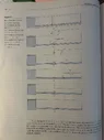
The water stops flowing because someone slammed the gate closed. The pressure spike ( post sound wave beginning to travel toward the sump) work to open the valve back up. Then the system returns to its lower state of pressure once the wave has made it to the inlet of the sump(river). The valve has to now be able to fall again under its own weight (fighting viscous drag as well) carrying enough momentum to slam itself shut again. We need a pressure drop below initial state to see this occur. I believe that pressure drop below initial state is characterized by the reflecting waves @Baluncore brings up, as is shown in the image below.

Image from Engineering Fluid Mechanics, Ninth Edition. Authors Crowe,Elger,Williams,Roberson
 

Attachments

  • IMG_3754.webp
    IMG_3754.webp
    140.7 KB · Views: 1
Last edited:
Reply
  • Like
Likes   Reactions: Baluncore
Okay, I stand corrected. Had been thinking about it and realised that, yes, there needs to be a moment of negative pressure for the waste valve to re-open. The extent to which that is rebound from water compression rather than a product of the pipe expanding and recoiling I am still thinking about. Recalling the one I made from purchased plans - very little fall of water, slower water flow, larger feed pipe, much slower cycle - I vaguely recall an option for including a spring to assist the re-opening, but, yes, that moment of negative pressure is needed.
 
Reply
  • Like
Likes   Reactions: erobz and Baluncore
Ken Fabian said:
Nothing like being wrong with confidence.
I know the feeling very well. :smile:
 
Ken Fabian said:
Okay, I stand corrected.

I wouldn't be too sure. Maybe you were on the right track to start with...

Ken Fabian said:
there needs to be a moment of negative pressure for the waste valve to re-open.

OR... maybe a moment of low enough positive pressure that the deadweight can overcome it and reopen the valve? And that moment will come when the K.E. of the moving water (plus some energy stored as compressed air) has been used up in raising some of the water against gravity?

I am veering towards the notion that the answer to "whether some degree of water compression is a necessary feature for the pump to work at all", depends critically on the design and optimization of the waste valve.

IMHO, the ideal waste valve will have an outflow-based closing threshold and a pressure-based opening threshold. If it isn't designed this way, then the system will rely on compression waves, rebound pulses etc. which is (IMHO) a suboptimal kludge.

Edit: Later today I will add a screenshot from Steve Mould's video, showing a model that he got a commercial pump manufacturer to build for him. This valve has features that suggest it complies with the ideal one I have described above. This company also has models using a venturi-based waste valve, which would be even better. OTOH, the waste valve in Steve's own 2D model isn't quite set up the same way.
 
Last edited:
Reply
  • Like
Likes   Reactions: Ken Fabian
Swamp Thing said:
I am veering towards the notion that the answer to "whether some degree of water compression is a necessary feature for the pump to work at all", depends critically on the design and optimization of the waste valve.
No matter how you optimize the valves, the main issue of the complete incompressibility assumption would still remain:

Keeping everything else the same, and letting the compressibility of the fluid tend to zero (or speed of sound to infinity), has following consequences for stopping the fluid by quickly closing the waste valve:
a) The peak pressure tends to infinity
b) The duration of that pressure spike tends to zero

So no matter how quickly the check valve opens, the overpressure is already gone, as it propagates instantaneously out of the induction pipe. Unless you build an infinitely long induction pipe for your completely incompressible fluid.

The fallacy, leading to assuming that less compressibility can only improve the efficiency, seems to come from considering only point a) above, and ignoring point b).
 
If there is doubt, couldn't we just compare the cited pump head of manufactured ram pumps to the theoretical ## \frac{\Delta p}{\rho g } = \frac{V^2 + Vc}{g} ## that we get from the Momentum Equation analysis? It's independent of design, its a hard (upper) limit using the water hammer theory.
 
We know the speed of sound in water, so we know it takes say 8 ms for the pressure wave to propagate up a 12-metre induction pipe, and then another 8 ms for the reflection to return, to cancel the pressure. That gives 16 ms for water to flow through the check valve into the air reservoir, then the waste valve reopens, and the stopped water begins to accelerate again.

The above process assumes sound travels through compressible water. If we over-build the induction pipe, the ram pump will perform as expected, but if we use a thin walled metal induction pipe, or a polymer pipe, the performance is not as good, or it fails to cycle. That tells us that it is the wave in the water, and not the expansion of the metal induction tube that is important. If the induction pipe is insufficient to constrain the water volume, then energy will be lost to the pipe wall.

A pressure wave in water propagates at about 1,450 m/s, while a pressure wave in steel propagates at about 4,500 m/s. A Shear wave in steel propagates at about 3,200 m/s. An s-wave does not propagate in a liquid.

As the waste valve closes, a pressure wave departs, with the fluid pressure expanding the induction pipe. That expansion travels with the pressure wave, but it also travels as a shear wave in the metal wall of the pipe, at about 3,200 m/s, outrunning the speed of sound in the water of 1,450 m/s. If there was significant expansion of the induction pipe, there would be a pressure drop in the water, immediately ahead of the positive pressure step.

The speed of a pressure wave in HDPE is about 2,450 m/s, but the shear wave propagates at only about 950 m/s. The s-wave induced in an HDPE pipe wall, will be left behind by the p-wave in the water, so there will not be a momentary drop in pressure ahead of the pressure rise in the water, even though the HDPE pipe expansion will be greater than that of a metal induction pipe.
 
1789233953264.webp


The vertical pipe is the discharge. If there is a check valve at its base, we don't have to worry about dynamics of the flow into that tube (Eventually the filling process will halt). moving the vertical pipe left or right has no consequence as there is no friction damping to consider in the idealization. The total head of the process once it halts is given by the Momentum Equation applied to the control volume above:

$$ \sum \boldsymbol{F} = \frac{ d}{dt} \int_{cv} \rho \boldsymbol{v} d V\llap{-} + \int_{cs} \boldsymbol{v}\rho ( \boldsymbol {V}\cdot d \boldsymbol{A} ) \tag{Momentum}$$

Sum of the Forces: ##PA - ( P + \Delta P ) A ##

Momentum Efflux term assuming uniform velocity, and density distributions over the inlet area ##A##: $$\int_{cs} \boldsymbol{v}\rho ( \boldsymbol {V}\cdot d \boldsymbol{A} ) = -\rho V^2 A$$

The is no Momentum Efflux at the outlet.

Momentum Accumulation term there are two regions to consider in the control volume for the integration( ahead of the sound wave and behind it). Assuming uniform velocity, and density distributions along the control volumes length the integrals compute to the bracketed terms: $$\frac{ d}{dt} \int_{cv} \rho \boldsymbol{v} d V\llap{-} = \frac{d}{dt} \left[ V \rho ( L - ct )A + 0 \cdot ( \rho + \Delta \rho)ctA \right] $$

The second term is zero because the flow velocity behind the wave is zero. After taking the derivative:

$$\frac{d}{dt} \left[ V \rho ( L - ct )A\right] = -\rho V c $$

Put it together:

$$ PA - ( P + \Delta P ) A = -\rho V c -\rho V^2 A $$

Which reduces to:

$$ \Delta P = \rho \left( V^2 + Vc \right) $$

In my opinion...No matter how the water hammer process works from here on out, this is as good as it gets. The system is going to stall when the head above the check valve reaches ## P_o/\rho g +\Delta P/\rho g ## .

In this model there is no friction in valves that exist, no viscous effects in the plumbing, *if conduit expands ## V ## slows*, etc...everything real about this pump design seems to add constructively to reduce ram pump performance from this point forward?

* I'm not sure about this, the increase in pressure behind the wave would increase the density behind the wave. The plumbing expands faster than ##c## and the velocity ##V## ahead of the wave would drop to conserve mass? I think it’s going to be vanishingly small order effect either way.
 
Last edited:
It is interesting thinking it through - not so much reading of references in this case; it is good for my brain, whilst noting that what I think sometimes leads to what is correct but sometimes not.

In this case it is turning out more complex than my initial thinking, or even my first few iterations. After more thinking I'm inclining more towards backflow from the non-return/feed valve and air chamber before it closes as the principle source of a time of negative pressure, by making a momentary backflow up the feedpipe. When that valve fully closes a moment of negative pressure occurs from the inertia of that backflow turning around. I am not certain of this of course.

I don't think I was wrong about everything and still think compressibility and pipe expansion make inefficiency - that if not for the need to re-open the waste valve (ie for a single hammer) uncompressible fluid and absolute rigidity and instantaneous non-return valve would deliver the most flow past the non-return valve.

There are multiple factors for the waste valve to re-open - weight of the valve (or potentially a spring), negative pressure from expansion of pipe followed by contraction that makes a small upward flow, which would make a moment of suction from that back flow inertia. There is an acoustic wave as Baluncore says, in the water column. But there is also backflow from the non-return valve before and as it closes. (I realise pipe expansion/contraction would also be an acoustic wave, a reverberation and not a single expansion/contraction, but (I think) dissipating fast enough to effectively act like just one for this purpose.)

Still thinking about the sound wave - and I keep thinking about how fast that would be and how strong and that is where I have lingering doubts. For expansion/contraction of the pipe also - although I think that may be slower and do more than the acoustic wave. But still too little, too fast?

Peak pressure of the water hammer is moderated by the non-return/check valve opening - my thinking about it says peak pressure is therefore limited by the head pressure moderated (increased somewhat) by the inertia of the water within the delivery pipe when it opens. Which limits the peaks of acoustic waves and pipe expansion/contraction.

My conclusion now - am not so confident as to call it final - is a bit of backflow from the air chamber before (and as) the non-return/feed valve closes makes a moment of negative pressure. Just because the volume of water moved by that will be more than the other factors.
 
Last edited:
A.T. said:
Keeping everything else the same, and letting the compressibility of the fluid tend to zero (or speed of sound to infinity), has following consequences for stopping the fluid by quickly closing the waste valve:
a) The peak pressure tends to infinity
b) The duration of that pressure spike tends to zero

If we think of this as a collision, (a) and (b) together don't mean that momentum isn't transferred and conserved. In abstract terms, is this not equivalent to a collision between two steel rods, or quartz rods, or whatever? In the pump case, the post-collision separation (rebound) might show up as a cavitation bubble, but momentum transfer would still take place?

The other point is that the air chamber makes this a buffered collision, so (a) and (b) are not strictly correct. The pressure would ramp up and down as the air compressed and decompressed, preventing cavitation IMHO?

Another perspective -- thinking in terms of transmission lines. The compressibility and density give rise to a characteristic impedance. When the incoming line tries to dump its current into the output line, the transient phenomena see each line as a resistor with value Z0, until such time as information can return from the far end.

Now if our air reservoir (capacitor) has an Xc << Z0, then the transient spike would be negligible and we would see a clean ramping up and down of the "voltage". The capacitor reduces the "bandwidth" of all the transient phenomena to a point where the length of the transmission lines is effectively zero compared to even the shortest wavelength component. Does this make sense at all?
 
Last edited:
Ken Fabian said:
After more thinking I'm inclining more towards backflow from the non-return/feed valve and air chamber before it closes as the principle source of a time of negative pressure, by making a momentary backflow up the feedpipe. When that valve fully closes a moment of negative pressure occurs from the inertia of that backflow turning around. I am not certain of this of course.
As pressure steps up in the pump chamber, the check valve lifts very slightly as water begins to pass into the air chamber. That check valve closes as soon as the pressure begins to fall. There is virtually no back flow through the check valve, which is normally held closed by the compressed air, at the pressure head of the outlet water column. The induction tube and the waste gate will still cycle, even if no water flows up through the check valve, or there is no check valve, or there is no air in the reservoir. Then the cycling will induce air through the pinhole, into the pump chamber, up through the check valve, into the reservoir. Excess air in the pump chamber, that might block priming of the air reservoir, will be vented through the waste valve during every cycle.

The waste valve is closed by the excessive flow of water, lifting the valve against its seat above. A spring-loaded "burst valve" operates on the same principle in a hydraulic circuit, blocking the flow and preventing a collapse, should a hydraulic line burst, resulting in excessive flow.

You can think of the acoustic pressure step and its cancelling reflection, as the way the closed waste valve finds out that the inlet to the induction pipe is open, and that there is only a low head of water pressure in the static induction pipe.

There is no back flow in the induction tube. The closing waste valve stops the water flow completely, which generates the pressure wave step. When the reflection returns, cancelling the pressure, the waste valve simply sinks into the still water, due to its mass and gravity, which then allows the flow to begin again from zero.

Swamp Thing said:
The other point is that the air chamber makes this a buffered collision, so (a) and (b) are not strictly correct. The pressure would ramp up and down as the air compressed and decompressed, preventing cavitation IMHO?
The air pressure does rise and fall in the air reservoir, but only very slightly as the volume of compressed air is much greater than the volume of water that passes during each cycle. The air reservoir, is the equivalent of the reservoir capacitor in a rectified power supply, while the check valve is the diode rectifier.
 
Swamp Thing said:
If we think of this as a collision, (a) and (b) together don't mean that momentum isn't transferred and conserved.
The moving fluid has a certain momentum that needs to be transferred in order to stop the fluid. Less compressibility means it is transferred over less time. Zero compressibility would mean it is transferred over zero time.

Swamp Thing said:
In abstract terms, is this not equivalent to a collision between two steel rods, or quartz rods, or whatever?
Yes. And if you assume perfectly rigid materials you get a momentum transfer duration of zero.

Swamp Thing said:
The other point is that the air chamber makes this a buffered collision, so (a) and (b) are not strictly correct. The pressure would ramp up and down as the air compressed and decompressed, preventing cavitation IMHO?
No, because the check valve is still closed when that pressure spike, lasting just one instant, occurs. Complete incompressibility means all the fluid in the induction pipe stops instantaneously, when the waste valve closes. There is no time period for ramping up and down.
 
Last edited: