Satellite Control System With Rate Feedback

Join the discussion
Ask a follow-up here, or get your own question answered by working scientists, mathematicians and engineers — people, not an autocomplete.
Real named experts · corrections over time · the nuance an AI answer skips
17 replies · 5K views
jj007
Messages
8
Reaction score
0
I'm trying to get the transfer function of this rigid control system that uses rate feedback to stabilize it. Using k=1 and kv=0
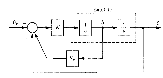
Capture_zps6fbe8d62.png


Attempt at a solution.
When kv=0, the rate feedback is removed.
In the block diagram, I moved the pickoff point and used the cascade rule to get [tex]1/s^2[/tex]
and the transfer function for the top portion is [tex]H(s)=\frac{(1/s^2)k}{1+(1/s^2)k}=\frac{k}{s^2((k/s^2)+1)}[/tex]
With the pickoff point moved you get [tex]\frac{1}{1/s}[/tex] at the bottom next to kv.
This is where I'm stuck. How do I get the complete transfer function? I would like to put it in matlab.

Thanks
 
Physics news on Phys.org
This looks like something you probably should have posted in the Homework section, just FYI.

What transfer function is it you want? Is it θ(s)/θ_r(s)?
 
milesyoung said:
This looks like something you probably should have posted in the Homework section, just FYI.

What transfer function is it you want? Is it θ(s)/θ_r(s)?

Yes please.
 
For K = 1, K_v = 0, you have a double integrator, 1/s^2, in a unity feedback configuration and the transfer function you posted, H(s), is the closed-loop transfer function θ(s)/θ_r(s) for this system.

In case you're looking for θ(s)/θ_r(s) with K, K_v only known to be real, you could apply block simplification for the inner loop first, then the outer one using the rule for negative feedback loops. You already used this rule once in finding H(s).
 
That's the only thing I'm not sure of...the block simplification. There's so many rules and I don't know which ones to apply here.
 
This was the first link on Google for 'block simplification':
http://www.msubbu.in/sp/ctrl/BD-Rules.htm

Have a look at rule 1, 2 and 6. Try simplifying your block diagram to a single system using those rules and post here if you get stuck.
 
Split up the summing junction and simplify the series inside the inner loop, rule 1 & 2:

sys1.jpg


Simplify the inner negative feedback loop, rule 6:

sys2.jpg


Do you understand those steps? How would you proceed?
 
milesyoung said:
Split up the summing junction and simplify the series inside the inner loop, rule 1 & 2:

sys1.jpg


Simplify the inner negative feedback loop, rule 6:

sys2.jpg


Do you understand those steps? How would you proceed?

Understood. Proceed by using rule 2 again and that's it? Looks like I was over complicating things.

Thanks
 
Rule 2 to simplify the series inside the loop, but what about the loop itself?
 
milesyoung said:
Rule 2 to simplify the series inside the loop, but what about the loop itself?

The output [itex]\theta[/itex] goes back into junction, which gives a transfer function of 1?
We're looking for [itex]\frac{θ(s)}{θ_r(s)}[/itex] right?
 
We want to simplify the block diagram so it looks like:

θ_r -> box -> θ

and nothing else. No loops!

Have a look at the step I did using rule 6. Doesn't that look like something you could do again?
 
Y=[itex]\frac{G1}{1+G1(1)}[/itex]= [itex]\frac{K}{s^2+s*K*K_v+K}[/itex]?
 
Ok. Last Question. For K=1 and K_v=0, how do I use this transfer function in MATLAB to get the Root Locus or Bode plot?
 
jj007 said:
Ok. Last Question. For K=1 and K_v=0, how do I use this transfer function in MATLAB to get the Root Locus or Bode plot?

If you have the Control System Toolbox you could use its suite of commands, e.g.:
tf
bode
rlocus

and so on. Have a look at their help pages and that of the toolbox itself.

If you don't have it, you could make your own functions to evaluate the transfer function for whatever range of parameters you're interested in and plot the results.
 
There is an rlocus function in MATLAB that will plot the root locus plot of a given transfer function.