I Sine laws of spherical singlets

  • I
  • Thread starter Thread starter difalcojr
  • Start date Start date
AI Thread Summary
Eugene Hecht's assertion that all aberrations cannot be made zero in systems with spherical surfaces is challenged, particularly for monocentric, biconvex lenses. The discussion centers on equations derived from sine laws that can theoretically yield zero spherical aberration (SA) under specific conditions, particularly at aplanatic points. However, participants agree that achieving a real image free of SA with a single spherical lens is impractical, as it effectively becomes a cemented doublet. The conversation also touches on the feasibility of using high-index materials to create such lenses, with costs and manufacturing challenges being significant considerations. Ultimately, the theoretical model presented could have implications for optical design, despite its practical limitations.
difalcojr
Messages
357
Reaction score
255
TL;DR Summary
spherical singlets with zero spherical aberrations
Eugene Hecht in his textbook "Optics" wrote, "We can be fairly certain that all aberrations cannot be made exactly zero in any real system comprising spherical surfaces." This is not true, actually.
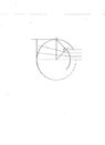
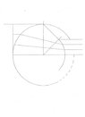
For a monocentric, biconvex, single lens of spherical surfaces, the following equations lead to projective models with zero spherical aberrations. Let n0 equal the index of refraction of the medium before the lens, n1 equal the index of the lens itself, n2 equal the index of the medium after the lens, r1 equal the radius of curvature of the anterior surface, and r2 equal the radius of the posterior surface. Then,
n1/n0 equals r1/r2 and n0/n1 equals n1/n2 .
These variables for indexes and curvatures combine in these two sine law equations to give rules for lens models that, for single frequencies, are optically "perfect"!
 
  • Care
Likes hutchphd
Science news on Phys.org
Do you refer to the aplanatic points of refracting spherical surface? SA can be exactly zero between aplanatic points. However, that is not the case for any arbitrary conjugation points. Changing the object position would change the spherical aberration.
Can you demonstrate an example of optical lens with only spherical surfaces making a real image of a real object free of the SA? Real means not a virtual. I doubt it can be made.
 
  • Like
Likes hutchphd
I agree with you that a spherically biconvex, single lens, having real object and real image and zero SA, cannot be made. This model is for projection lenses.
Yes, I do refer to Huygens' aplanatic points within refracting spherical surfaces. Thank you for your insight. The posterior radius itself is exactly the length from center of lens to his aplanatic points of exact focus. They are the limit points for the model's range of valid incident waves, converging, planar, and diverging.
As far as any arbitrary points on any incident wave, for this model, again, SA is zero for these too. Incident and transmitted angles are the same at both surfaces for every ray within every spherical wave. What comes, goes out the same, magnified.
I have not seen a lens of the model's shape made.
 
The aplanatic spheres is widely used in the optical design, look at microscopes or condesor systems, for example.
design using the aplanatic spherical surfaces.png
 
Great diagram. Thank you. Hope my attached diagram will help now too.
So, in addition to finding the position of the aplanatic point in a sphere, Huygens found the perpendicular distance to the marginal, refracted ray in the sphere. Which is the bisector, and he saw this was the point where the rays first started to cross each other. The lengths are equal and radius2 here.
For the diagram, n0 equals 1, n1 equals the square root of 2, r1 equals 1, and the second incident angle was set equal to the first for the marginal ray, set at 90 degrees.
Here's how to get to my initial sine relations: use the law of refraction with its angles for the first surface, and a sine law equation again for the enclosed triangle. Substitute values and solve for r2. See what you think.
 

Attachments

  • Image (102).jpg
    Image (102).jpg
    7 KB · Views: 86
  • Image (100).jpg
    Image (100).jpg
    9.5 KB · Views: 93
What is n3 would be? According to picture ray is refracting to the media with n3, and n3>n2.
 
difalcojr said:
Then,
n1/n0 equals r1/r2 and n0/n1 equals n1/n2 .
Assuming n0 = 1, n1 = 1.4, and n2 = 1:
n0/n1 = 0.666...
n1/n2 = 1.4

How does n0/n1 = n1/n2?
 
No, not n3. You mean n2, for the three indices that are needed, I am using n0, n1, and n2 only. But, to answer your question, what would n2 be? To get exactly zero SA, it would equal n1 squared, divided by n0. Value of 2 in this example. Look at the second relation again in the first posting to see the sine relation again. This is the easiest example to show, a planar wave. Also, for the indices shown, it is a 2:1 reduction in size.
 
Drakkith said:
Assuming n0 = 1, n1 = 1.4, and n2 = 1:
n0/n1 = 0.666...
n1/n2 = 1.4

How does n0/n1 = n1/n2?
No, n2 does not equal 1. n2 equals n1 squared, divided by n0. Look at the sine relation again in the first posting. So, it equals 2 in this example. Thks for your interest.
 
  • #10
difalcojr said:
No, n2 does not equal 1. n2 equals n1 squared, divided by n0. Look at the sine relation again in the first posting. So, it equals 2 in this example. Thks for your interest.
What relation? I see no such relation in the first post.
 
  • Like
Likes berkeman
  • #11
Yes, it is there. Look again. It is n0/n1 equals n1/n2. Solve for n2 from this equation. Thank you.
 
  • #12
difalcojr said:
Yes, it is there. Look again. It is n0/n1 equals n1/n2. Solve for n2 from this equation. Thank you.
Forgive me, I haven't taken optics in years. If there is a sine somewhere in there it would help if you explicitly posted it.
 
  • #13
Oh, you are absolutely right. I have confused it. My apologies. I should have said. Just plug the values into the initial equations given, and solve for radius2 and index2.
Instead, I just added an alternate method I had used myself, initially, using the law of refraction, to get to those initial relations in the first post. The law of refraction, with the sines of the incident and transmitted angles I had not mentioned at all! My bad on that one, sorry. In that method for solution, the sines term drop out of the equations. This model is independent of angle.
 
  • #14
Okay. For n0 = 1, n1 = 1.4, and r1 = 1, I get r2 = 0.7143 and n2 = 1.96.
Any idea how many materials have an optical refractive index close to 2?
 
  • #15
Yes, that's the ticket! Correct and thank you. The diagram had used the square root of 2 for calculating and plotting ease.
Not many, I would say, in answer to your question. For solids, anyway. 2 is a high and limiting index number for this model. If the second medium was liquid, it could possibly be contained and "doped" to an exact index of refraction needed. Would this be true?
 
  • #16
Probably. There are at least a few liquids that have refractive indices around 2. How well their other properties would work for this, I don't know. And there may some significant difficulty or cost in manufacturing a hollow 'lens' to hold the fluid. I guess the issue really boils down to the cost of making aspherics vs the cost of making a fluid-filled lens with the appropriate fluid.
 
  • #17
Thank you for conversing on this model. Yes, you are right; it does always boil down to the cost in the end, doesn't it, in business and industry, anyway? There may be other significant difficulties, also, agreed. I am not in the industry nor knowledgeable in this matter. The model is entirely theoretical at this point. Some one of your readers could figure it all out, I am sure. Spherical molds are cheapest, I think.
The possibilities are limitless. Either the lens or the medium after it could be solid or liquid, even a gel or gas, possibly. I can think of some uses in micro and macro devices. Zero SA.
Here's a couple more plots to show more examples for your consideration.
Image (101).jpg
60degree.jpg
 
  • #18
If I may add just a few more pictures, it should let you see what these might look like. The first diagram again for clarity, with the equations shown, and also an array of cemented doublets in sequence with incident angles and first and second radii shown. The third,
model.jpg
Image (103).jpg
Image (104).jpg
last radius for the doublets is arbitrary.
 
  • #19
Drakkith said:
There are at least a few liquids that have refractive indices around 2.
There is Ohara high index optical glass S-LAH79 with about 2, used for ball lenses.
 
  • Like
Likes difalcojr
  • #20
Refractive index of diamond is 2.42 I believe.
 
  • #21
hutchphd said:
Refractive index of diamond is 2.42 I believe.
If I had an eyepiece lens made out of diamond...
I would very quickly not have an eyepiece lens made out of diamond...
 
  • Haha
  • Like
Likes hutchphd and berkeman
  • #22
Here's a last picture for the week, if no complaints yet. Thanks. A sequence showing rays and some ray extensions, both front and back. First index is the square root of 2 again. Angles given are for half-waves. (Angles in the last big array posted were full wave values.) Incident angle of waves not to be confused with incident angles in the law of refraction at the surfaces. Will you all agree yet to zero SA for this model?
Image (105).jpg
 
  • Like
Likes Gleb1964
  • #23
If that is what the math says then I agree with it. However, note that we really don't have a singlet anymore. That typically implies a single lens inside a single medium such that the refractive index on both sides is the same. You've essentially made a cemented doublet.
 
  • Like
Likes difalcojr, hutchphd and berkeman
  • #24
Yes, I agree with you that this is not a singlet that we typically think of as a lens immersed in a single medium. Defined like that, it's not a singlet, no. So, it's really a cemented doublet when capped off. That's OK, too. It still disproves the current thinking, as expressed in Hecht's quote pertaining to spherically surfaced lenses not being able to zero SA. Thanks for all your needed clarifications.
Yes, I think those first two equations hold for all the waves up to the aplanatic point, for all the calculating I've done to check points plotted in the pictures.
So, this should be big news for physics, geometrical optics and Huygens, and I hope someone as yourself or one in your audience, can made good use of this model. It should have been found about 350 years ago. Huygens had the geometry then and the second radius.
 
  • #25
Versions of it have been previously known for aspheric surfaces. It is why one parabolizes a mirror.
Double sided lenses are much more difficult to produce and absent machine tools and other modern techniques only of academic interest.
So it is a doublet and does not violate any historic strictures as near as I can tell. Specifically it does not violate Hecht, IMHO..
 
  • Like
Likes difalcojr
  • #26
difalcojr said:
It still disproves the current thinking, as expressed in Hecht's quote pertaining to spherically surfaced lenses not being able to zero SA.
I don't really see it that way. A singlet is almost by definition a single lens with the same medium on both sides. Anything else is either a complex optical system with more than a singlet, or a very strange optical system where a lens sits in two different fluid mediums, which you basically never encounter.

But don't let that detract from the work you've done. Optical design is not a trivial process by any means.
 
  • Like
Likes difalcojr
  • #27
hutchphd said:
Versions of it have been previously known for aspheric surfaces. It is why one parabolizes a mirror.
Double sided lenses are much more difficult to produce and absent machine tools and other modern techniques only of academic interest.
So it is a doublet and does not violate any historic strictures as near as I can tell. Specifically it does not violate Hecht, IMHO..
Hecht is only reporting the facts of known science on the subject of spherical aberration. His textbook "Optics" is the best ever, and he may be one of the greatest, general teachers ever. His text has long been my guidebook. I think you can see his uncanny intelligence just in the way he only says "fairly certain" in the quote of my initial post. He hedges his bets and does not discount it completely. I had to look up IMHO to see what it meant. Thanks. Hecht cannot be violated.
On your 2.42 index diamond mentioned in a previous post, I think I see your doublet there in the array. Just kidding. In a micro device, maybe. Maybe only use the paraxial area for diamonds.
 
  • #28
Gleb1964 said:
There is Ohara high index optical glass S-LAH79 with about 2, used for ball lenses.
I think I see your ball lens in that array of cemented doublets. Just kidding.
Your insight of Huygens' aplanatic point is a main point of this design model. Thanks again.
 
  • #29
Drakkith said:
I don't really see it that way. A singlet is almost by definition a single lens with the same medium on both sides. Anything else is either a complex optical system with more than a singlet, or a very strange optical system where a lens sits in two different fluid mediums, which you basically never encounter.

But don't let that detract from the work you've done. Optical design is not a trivial process by any means.
First, thks for the encouragement.
The model is an odd apple, for sure, if you've never seen it. The pictures are for full waves too. Actual uses would probably be for smaller areas nearer the central axis. A couple of off-axis plots can help you see more.
Image (106).jpg
Image (107).jpg
 
  • Like
Likes Drakkith and hutchphd
  • #30
Drakkith said:
Forgive me, I haven't taken optics in years. If there is a sine somewhere in there it would help if you explicitly posted it.
Here's the missing sine laws I confusingly left out of the equations first posted for this model. Here's all the relations now. They all have the same value, that of the refractive ratio. Square root of 2 here in the diagrams. Surface angles are now included for the two surfaces.

sine(incident1) = index1 = index2 = sine(incident2) = radius1
sine(transmit1) index0 index1 sine(transmit2) radius2

It's easy enough, basic, really, but not trivial, I agree.
 

Attachments

  • Image (109).jpg
    Image (109).jpg
    5.3 KB · Views: 106
  • Like
Likes Drakkith
  • #31
Image (110).jpg

I really appreciate the fact that three of you have replied to me in this physics forum over the past week and given me your critical thoughts on a new lens model I wanted to show to all. One more important point of Huygens is useful, I think, to show now, for further clarification.
Here's a copy of his diagram of the aplanatic point of perfect focus within the sphere (without the construction lines). It is from his "Treatise on Light". He was writing about his re-trace of the conics sequence and ovals of Descartes. He says: "But it is worthy of remark, that in one case this oval becomes a perfect circle, namely when the ratio of AD to DB is the same as the ratio of the refractions, here as 3 to 2, as I observed a long time ago."
So, here's another refractive ratio, as seen on the horizontal axis line ratio Huygens found. He used 1.5 for his glass index models. In the above diagram, the line lengths ratio is the square root of 2, the same value as the other ratios of this model.
 
  • Like
Likes Gleb1964 and Drakkith
  • #32
Image (111).jpg

This goes with the earlier sequences shown. Might help. Marginal rays of various, incoming waves and their refracted chords inside a sphere are shown. Also, a source point right at the edge of the first surface, and the aplanatic ray with its extension to horizontal axis, these two angles at the limit points of this model. Bisectors to the refracted chords are shown, and you can see the extent of the second radius needed for each wave at its marginal point.
 
  • Like
Likes Drakkith
  • #33
Drakkith said:
If that is what the math says then I agree with it. However, note that we really don't have a singlet anymore. That typically implies a single lens inside a single medium such that the refractive index on both sides is the same. You've essentially made a cemented doublet.
Yes, cemented doublets, thanks, though I think I could argue the point for a singlet too a bit further.
Also, I have not really proven anything yet, just shown diagrams that I said I plotted. They could just be AutoSketch pictures. Your caution seems like Hecht's here, reliable and needed, I think. Unless you may accept the fact that the model is independent of incoming angle that showed up in your earlier alarm about the missing sine law relations in the first post.
To my knowledge a perfect lens must also have constant magnification and constant optical path lengths, as per Maxwell's conditions?
 
  • #34
Not sure. But I did find the following snippet from this site:

  • Notwithstanding eight propositions about perfect optical systems, Maxwell ended with a ninth proposition that dampened the hopes of would-be instrument designers. An optical system can at best produce a perfect image only if the magnification is equal to the ratio of refractive indices in image and object space. Since in the usual circumstances both object and image are in air then one can’t make a perfect image with any ‘magnification’ other than unity. A truly plain mirror, for example, creates a perfect image but anything designed to magnify won’t. This applies to cameras, microscopes, telescopes and so on.
 
  • Informative
Likes berkeman
  • #35
Drakkith said:
Not sure. But I did find the following snippet from this site:

  • Notwithstanding eight propositions about perfect optical systems, Maxwell ended with a ninth proposition that dampened the hopes of would-be instrument designers. An optical system can at best produce a perfect image only if the magnification is equal to the ratio of refractive indices in image and object space. Since in the usual circumstances both object and image are in air then one can’t make a perfect image with any ‘magnification’ other than unity. A truly plain mirror, for example, creates a perfect image but anything designed to magnify won’t. This applies to cameras, microscopes, telescopes and so on.
Well, that's an interesting site. I did not know of 9 propositions al all. But I just found what Maxwell also wrote from his source listed on that web page. I'll write it as it is shown in the text with the italics used:

"A perfect instrument must fulfill three conditions:
I. Every ray of the pencil, proceeding from a single point of the object, must, after passing through the instrument, converge to, or diverge from, a single point of the image. The corresponding defect, when the emergent rays have not a common focus, has been appropriately called (by Dr. Whewell) Astigmatism.
II. If the object is a plane surface, perpendicular to the axis of the instrument, the image of any point of it must also lie in a plane perpendicular to the axis. When the points of the image lie in a curved surface, it is said to have the defect of curvature.
III. The image of an object on this plane must be similar to the object, whether its linear dimensions be altered or not; when the image is not similar to the object, it is said to be distorted.
An image free from these three defects is said to be perfect."
 
  • Like
Likes Drakkith
  • #36
So, this model does not fulfill Maxwell's first condition.
My take on the reason for this, is that the model herein is a projection lens and has no change in the wave angles. What goes in, comes out with same angle, magnified, and the entire wave is magnified.
Also, Maxwell's condition is for a thin lens with an incident planar wave, a lens ideally having parabolic surfaces to get zero SA. Thin lens equations don't fit this model well at all, if you have tried any. For the mechanical drawings, only geometry and trigonometry was needed!
 
  • #37
Image (116).jpg

A diagram may help more, but it's a bit messy, sorry. Planar wave again incoming and its refraction pattern of SA shown, the caustic, believe it's called. Also shown is the normal, second surface output flipped around, so its output is now the input. You can see that its refraction pattern is the exact mirror image of the first surface. Its refractive ratio is the inverse of the other. One pattern is a real image, the other a virtual image. This model matches the caustics of all the waves like this. At that point where the rays begin to cross each other, the bisector point of the marginal, refracted ray the sphere. That bisector length that Huygens found.
The model lens is afocal, no internal focus. Of course, it can project or receive from either direction. It is different from thin lenses in many ways, for sure.
 
  • #38
Here's my favorite picture for relief. 180 degrees diverging, both Huygens' points shown, maximum extension of radius2. No coincidence that it looks like a "Dutch-cut" haircut too? Huygens is the Dutchman.
Image (117).jpg
 
  • Like
Likes Drakkith
  • #39
difalcojr said:
View attachment 330275
A diagram may help more, but it's a bit messy, sorry. Planar wave again incoming and its refraction pattern of SA shown, the caustic, believe it's called. Also shown is the normal, second surface output flipped around, so its output is now the input. You can see that its refraction pattern is the exact mirror image of the first surface. Its refractive ratio is the inverse of the other. One pattern is a real image, the other a virtual image. This model matches the caustics of all the waves like this. At that point where the rays begin to cross each other, the bisector point of the marginal, refracted ray the sphere. That bisector length that Huygens found.
The model lens is afocal, no internal focus. Of course, it can project or receive from either direction. It is different from thin lenses in many ways, for sure.
better diagramView attachment 330296
 
  • #40
difalcojr said:
View attachment 330275
A diagram may help more, but it's a bit messy, sorry. Planar wave again incoming and its refraction pattern of SA shown, the caustic, believe it's called. Also shown is the normal, second surface output flipped around, so its output is now the input. You can see that its refraction pattern is the exact mirror image of the first surface. Its refractive ratio is the inverse of the other. One pattern is a real image, the other a virtual image. This model matches the caustics of all the waves like this. At that point where the rays begin to cross each other, the bisector point of the marginal, refracted ray the sphere. That bisector length that Huygens found.
The model lens is afocal, no internal focus. Of course, it can project or receive from either direction. It is different from thin lenses in many ways, for sure.
better diagram
Image (118).jpg
 
  • #41
hutchphd said:
Double sided lenses are much more difficult to produce and absent machine tools and other modern techniques only of academic interest.
Yes, agreed, but in molds could be mass produced, probably. Zero SA should be very attractive for a planar wave. What about uses in electronics? Say in signalization devices? Or microscopes/telescopes?
The model's dimensions are simple equations, its shape the same for every wave.
It needs a lot more academic interest, though, I think, now. Due it is something new. It's a lot to digest if you have never seen such a thing.
I only have a few more diagrams to finish up explaining the model. Thank you for your good criticism.
 
  • #42
I'd say do a full raytrace before trying to consider what the system would be good for. SA might be fully corrected for, but what about other aberrations?
 
  • Like
Likes Gleb1964 and difalcojr
  • #43
Agreed. Is there existing trace software that can get values for all the positions I've plotted? I used a trigonometric trace and AutoSketch.
What other aberrations? Chromatic? Not sure of that. Have only traced using one index number so far. Might be a big problem for color images, surely. I can think of another lens it absolutely would not be used for. Eyeglasses.
 
  • #44
There are dedicated ray tracing software that will plot all your aberrations, but don't I have a link to one right now. A quick google search should turn up some results.

Edit: You might try Optical Ray Tracer. I haven't used it before, but it's a free program that might be what you need. You can find it here: https://arachnoid.com/OpticalRayTracer/
 
Last edited:
  • Like
Likes difalcojr
  • #45
Thks. I'll check it out today. Well, there won't be any SA aberrations to plot, I'm contending. Program looks interesting. But to go back to the topic of the initial post, too, here's Huygens' other diagram with XN equaling the second radius. His ray/wave measurements diagram. Not sure what software he was using.

.................................
Image (119).jpg
 
  • Haha
Likes Drakkith
  • #46
Here's a 30 degree incoming wave. A very strange optical system indeed. Hope you may like this plot. Reminds me of the old SF movie, The Day the Earth Stood Still. Do you know that one?
Image (120).jpg
 
  • #49
Now I know why mathematicians are so special, and why I'm not a mathematician. Wow. Is that it what is takes to find exact position points for a parbolizing, second surface? And they can mass produce molds for those calculated shapes? Stupendous achievement of mathematics.
Looks like the spherical model could do some of the same things except for the real-real examples. Good problem for a cost analysis, maybe, for spheric/aspheric vs. spheric/spheric molds. For someone else.
 
  • Like
Likes hutchphd and Drakkith
  • #50
Drakkith said:
There are dedicated ray tracing software that will plot all your aberrations, but don't I have a link to one right now. A quick google search should turn up some results.

Edit: You might try Optical Ray Tracer. I haven't used it before, but it's a free program that might be what you need. You can find it here: https://arachnoid.com/OpticalRayTracer/
I chked it, Optical Ray Tracer. Thks. Could not get it to produce the model shape, but it's probably a good program for thin lenses, I assume.
I don't need a ray trace program, though. My own for this model works fine. It is on an old, discontinued spreadsheet called Improv. Made by Lotus before IBM gobbled them up. I just don't think there's software that can do thick, spherical tracing, anyway.
 
Back
Top