Solar panel with circuit inside a PC box -Not working

AI Thread Summary
The discussion revolves around a solar panel setup placed inside a PC box that is experiencing charging issues due to high internal temperatures reaching around 60°C. Despite generating 300mAh, the battery fails to charge when enclosed, likely due to the driver board's thermal response, which may prevent charging at elevated temperatures. Suggestions include using thermally conductive potting materials and copper plates to dissipate heat, although concerns about maintaining an IP68 waterproof rating complicate this. The controller board may also be shutting down charging due to temperature thresholds. Overall, addressing heat management is crucial for the system's functionality.
Madhumkm12
Messages
2
Reaction score
0
TL;DR Summary
Solar panel and circuit not working as intended inside a Polycarbonate box.
Hi,
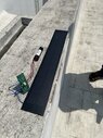
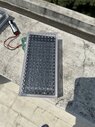
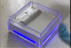
I am trying to build a product where i am placing a solar panel along with a driver board inside a Polycarbonate housing and closing it with a ABS cover at the back.
The driver board is soldered at the back of the solar panel and placed inside the PC box. Then a RTV(silicone sealant for leds ) layer is applied to hold still the setup inside the PC box. Then a 2 potting component is mixed and poured to make it waterproof IP68.

Here comes the problem. The panel is generating around 300mah when the panel board and the battery is outside in open air and the battery goes from 2.9v to 4v. But when the same setup is placed inside the PC box and kept for testing the battery is not getting charged. Still the solar panel generates the same 300mah current inside the box as well.

The doubt is whether the driver board is acting weird inside the PC case as the temperature inside the box is around 60'C and since the back is also covered there is a hot air inside thats not circulating. So some thermal reaction is happening.
How to over come this situation. There is no way i can make an air vent or Heat sink because in order to achieve IP68 i need to seal with potting.

Please help me out with a solution on this or the way it has to be approached
 
Engineering news on Phys.org
Welcome to PF.

Can you post some pictures? (Use the "Attach files" link below the Edit window.)

Also, can you consider a metal enclosure and thermally conductive epoxy to help get the heat out of the enclosure?
 
There is no possibility to go for a metal enclosure as we are putting LED to light up at night. so need a transparent material so only chose PC. which allows 88% of light inside. Tested on that.
we use Potting which is thermally conductive only so that it doesn't allow external heat inside and absorb from the panel or driver board as well.

Before doing this we try to test in once before pouring potting. But now there is an anomaly caused because of this charging issue
 

Attachments

  • MicrosoftTeams-image (8).jpg
    MicrosoftTeams-image (8).jpg
    55.1 KB · Views: 63
  • MicrosoftTeams-image (7).jpg
    MicrosoftTeams-image (7).jpg
    57.5 KB · Views: 65
  • potting.png
    potting.png
    114.1 KB · Views: 72
Madhumkm12 said:
The doubt is whether the driver board is acting weird inside the PC case as the temperature inside the box is around 60'C and since the back is also covered there is a hot air inside thats not circulating. So some thermal reaction is happening.
The battery has three wires so it's likely with a thermistor, which is monitored by the controller board. It'll stop charging if the temperature is too high.
The controller will likely monitor its own temperature too and shut down if it is too high.
Though it should still charge periodically. Just not full time. You should be able to check that.

Since it's just the normal operation I guess the only thing you can do is to remove the heat and maintain stable temperature (for both the battery and the controller).
Maybe you can add some copper plates below the potting. But this will require some engineering...
 
While I was rolling out a shielded cable, a though came to my mind - what happens to the current flow in the cable if there came a short between the wire and the shield in both ends of the cable? For simplicity, lets assume a 1-wire copper wire wrapped in an aluminum shield. The wire and the shield has the same cross section area. There are insulating material between them, and in both ends there is a short between them. My first thought, the total resistance of the cable would be reduced...
Hi all I have some confusion about piezoelectrical sensors combination. If i have three acoustic piezoelectrical sensors (with same receive sensitivity in dB ref V/1uPa) placed at specific distance, these sensors receive acoustic signal from a sound source placed at far field distance (Plane Wave) and from broadside. I receive output of these sensors through individual preamplifiers, add them through hardware like summer circuit adder or in software after digitization and in this way got an...
I am not an electrical engineering student, but a lowly apprentice electrician. I learn both on the job and also take classes for my apprenticeship. I recently wired my first transformer and I understand that the neutral and ground are bonded together in the transformer or in the service. What I don't understand is, if the neutral is a current carrying conductor, which is then bonded to the ground conductor, why does current only flow back to its source and not on the ground path...
Back
Top