acrimius
- 6
- 0
1. Situation and Variables:
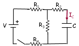
A circuit is constructed with four resistors, one capacitor, one battery and a switch as shown. The values for the resistors are: R1 = R2 = 30 Ω, R3 = 66 Ω and R4 = 113 Ω. The capacitance is C = 64 μF and the battery voltage is V = 12 V. The positive terminal of the battery is indicated with a + sign.
2. Sub-question:
After the switch has been closed for a very long time, it is then opened. What is Q(topen), the charge on the capacitor at a time topen = 786 μs after the switch was opened?
3. Relevant Equations:
Kirchhoff's Loop Rule: [tex]\Sigma V_l = 0[/tex]
Kirchhoff's Node Rule: [tex]I_i = I_o[/tex]
[tex]V_C = \frac {q} {C}[/tex]
For a discharging circuit:
[tex]q(t) = q_o e^\frac {-t} {\tau}[/tex]
4. Attempt:
When the switch is closed initially and time goes to infinity, the capacitor charges up and reaches it's capacitance, which I found the max charge, qo to be about 243μC.
Then for a discharging circuit, we have the equation I gave above q(t). I believe my issue is finding tau, which is RC. I have been using [tex]R = R_1+R_2[/tex] but that hasn't been correct. I've tried different combinations of resistors but I'm not quite getting it.
A circuit is constructed with four resistors, one capacitor, one battery and a switch as shown. The values for the resistors are: R1 = R2 = 30 Ω, R3 = 66 Ω and R4 = 113 Ω. The capacitance is C = 64 μF and the battery voltage is V = 12 V. The positive terminal of the battery is indicated with a + sign.
2. Sub-question:
After the switch has been closed for a very long time, it is then opened. What is Q(topen), the charge on the capacitor at a time topen = 786 μs after the switch was opened?
3. Relevant Equations:
Kirchhoff's Loop Rule: [tex]\Sigma V_l = 0[/tex]
Kirchhoff's Node Rule: [tex]I_i = I_o[/tex]
[tex]V_C = \frac {q} {C}[/tex]
For a discharging circuit:
[tex]q(t) = q_o e^\frac {-t} {\tau}[/tex]
4. Attempt:
When the switch is closed initially and time goes to infinity, the capacitor charges up and reaches it's capacitance, which I found the max charge, qo to be about 243μC.
Then for a discharging circuit, we have the equation I gave above q(t). I believe my issue is finding tau, which is RC. I have been using [tex]R = R_1+R_2[/tex] but that hasn't been correct. I've tried different combinations of resistors but I'm not quite getting it.
Last edited by a moderator: