Frank-95
- 51
- 1
Hello. I would need some clarifications about the impulse response of a RC circuit.
1. Homework Statement
Find the impulse response relative to the vc(t) voltage.
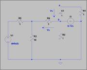
NOTE: delta(t) is the exact dirac's delta of infinite amplitude, not an approximated peak.
δ(t) = d θ(t) / dt
First of all I have a doubt of theoretical nature. If we know that capacitor's voltage is a continuous function (vc(0-) = vc(0+), and know that vc = 0 for t < 0, how can voltage change? Shouldn't it remain 0 for the impulse duration, considering the circuit completely ideal?
Anyway, is it correct to consider the impulse source as a step one, and then derivate the function?
Specifically talking, I found the Thevenin equivalent between a and b, and it comes out:
Rth = 1,6344 Ω
Vth = -0.3313 V
Then I calculate the step response as:
vcθ(t) = -0.3323 θ(t) (1 - e-t/1.6344)
From here is it correct to just derivate this function to get the impulse response?
vcδ(t) = -0.3323/1.6344 e-t/1.6344
Thank you very much.
1. Homework Statement
Find the impulse response relative to the vc(t) voltage.
NOTE: delta(t) is the exact dirac's delta of infinite amplitude, not an approximated peak.
Homework Equations
δ(t) = d θ(t) / dt
The Attempt at a Solution
First of all I have a doubt of theoretical nature. If we know that capacitor's voltage is a continuous function (vc(0-) = vc(0+), and know that vc = 0 for t < 0, how can voltage change? Shouldn't it remain 0 for the impulse duration, considering the circuit completely ideal?
Anyway, is it correct to consider the impulse source as a step one, and then derivate the function?
Specifically talking, I found the Thevenin equivalent between a and b, and it comes out:
Rth = 1,6344 Ω
Vth = -0.3313 V
Then I calculate the step response as:
vcθ(t) = -0.3323 θ(t) (1 - e-t/1.6344)
From here is it correct to just derivate this function to get the impulse response?
vcδ(t) = -0.3323/1.6344 e-t/1.6344
Thank you very much.