diy-er said:
TL;DR Summary: vertical square steel tube construction load
I have a VERTICAL standing square tube 1.25" x 1.25" x 1/16" thick.
Length/Height = 79"
Material = steel
How do you determine its max load capacity for this tube when mounted vertically?
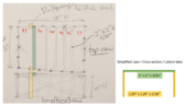
I plan to use 18 of these vertical posts, evenly spaced, creating an 83" x 131" rectangular structure.
They will be welded together on the top, as well as on the bottom, by 2" steel L-bars (3/16" thick), 4 pieces of 83" length, and 4 are 131" long.
Next I will weld a cross (on all 4 sides for structural integrity), made with steel flat bars of 1.25" x 3/32" thick.
Finally it will have the top connecting the long sides, with 5 horizontally mounted, evenly spaced 2" x 2" x 3/32" square steel tubes.
My question is what the load capacity is per post, per square foot, and/or for the entire stucture.
View attachment 321550
View attachment 321551
Thank you
What's the worst thing that could happen if the structure fails? Will lives be in danger?
I'll provide some approximate numbers but
if the failure of this structure has real consequences it should be analyzed in detail by a professional team. I am not responsible for what happens to this structure once built. With that said, let's see the problem.
Failure is dependent on the kind of load applied to the system and I am not certain I'm understanding how you will be loading it in the first place.
On the other hand, I have a few doubts about the geometry of the structure but it seems clear enough from the drawings to tackle the problem.
For the calculations, I'll simplify the problem using conservative approximations along the way.
- I will simplify the 3D problem to a 2D one by solving a key cross-section of the structure.
- I will ignore the diagonal beams.
- I will ignore shear loads because their contribution is typically negligible for slender beams when compared with normal stresses.
- I will consider failure happens when the elastic limit is surpassed.
- Stress at welding points will not be considered.
- I will not consider failure due to buckling. There are several vertical posts so the inertia of the structure is huge. The vertical posts are kind of bracing each other.
- Localized buckling due to bending will not be considered.
- I'll consider all beams to be made of A501 Hot Formed Carbon Steel Structural Tubing - Grade A.
- I will consider ALL the weight is being supported by just ONE beam on top of the cage and carried only to the two nearest vertical posts. This is a very conservative case because most likely you will have a distributed load on the rooftop that will be taken by multiple horizontal and vertical beams but since I'm lacking more detailed information I'll consider the worst-case scenario I can imagine.

I could derive the formulas for such a case but since it's a pretty common scenario there are already tabulated results about it.
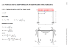
I am aware Spanish is most likely not your first language but the diagrams and formulas in the following picture are clear enough to post them here as reference.
Source: Universidad politécnica de Valencia
https://www.researchgate.net/publication/308119545_FORMULARIO_PARA_VIGAS_Y_PORTICOS
The worst-case scenario will be when ##m=n## which will result in the load applied in the middle. It is a critical case because it causes the greatest bending moments on the beams.
From the description of the problem by the OP it is possible to define:
- Vertical posts are square tubes 1.25" x 1.25" x 1/16" thick. Therefore, the moment of inertia of the section will be ##I=\frac{a^{4}-b^{4}}{12}##. Where ##a=0.03175m## and ##b=0.028575m##.
https://www.engineersedge.com/calculators/section_square_case_4.htm
Then, ##I_1 = 2.912*10^{-8}m^{4}##.
- The vertical posts will be working in compression too so I will need their section which is ##S_1 = a_1^{2}-b_1^{2}=0.000191532m^{2}##
- The horizontal beams are 2'' x 2'' x 1/16'' so ##a_2=0.0508m## and ##b_2=0.046m##. Using the same formulas as for the posts it's possible to obtain ##I_2 = 1.262*10^{-7}m^{4}##.
- The height of the structure is ##h = 79'' = 2m##
- The length of the critical beam is ##L = 83'' = 2.11m##
- From the previous defined values it is possible to obtain ##k=\frac{I_2h}{I_1L}=2.356^{-6}##
Because of the symmetry of the problem ##(m=n=\frac{L}{2})##, the formulas can be simplified:
- ##M_A = M_D =\frac{PL}{8(k+2)}##
- ##M_B = M_C =-\frac{PL}{4(k+2)}##
- ##M_P = \frac{PL}{4} + M_b = \frac{PL}{4} -\frac{PL}{4(k+2)}##
From previous points, we have seen ##k=2.356^{-6}##. Since it's always with a ##+2## and ##2 \gg k## we can then use the approximation ##k=0## to further simplify the equations for the bending moments.
- ##M_A = M_D =\frac{PL}{16}##
- ##M_B = M_C =-\frac{PL}{8}##
- ##M_P = \frac{PL}{4} + M_b = \frac{PL}{4} -\frac{PL}{8} =\frac{PL}{8} \rightarrow M_P = -M_B##
The maximum load ##{\color{Red} P}## will happen when any of the sections in the beams reach the maximum stress. I will then find the maximum stress at the critical sections as a function of ##{\color{Red} P}##.
For the
horizontal beam, the max stress will be at sections A, C, and P because they all suffer the same bending moment and they all have the same section.
##\sigma_{max} = \frac{My_{max}}{I} \rightarrow M_{y_2}=\frac{2I_2\sigma_y}{a_2}##
The horizontal beam will fail when ##M_P = M_{y_2} \rightarrow \frac{PL}{8}=\frac{2I_2 \sigma_y}{a_2} \rightarrow P_{max_2} = \frac{16I_2\sigma_y}{La_2}=4712N \approx 480kg \approx 1058lbs##
For the
vertical beam, the max stress will be due to the combination of the compression and the bending moment. The critical section will be either B or C.
NOTE: I'll use a positive value of ##M_B
##. Signs are just to define if it is compression or tension and that's not relevant for this problem.
##\sigma_{max_1} = \frac{a_1M_B}{2I_1}+ \frac{P}{S_1} \rightarrow P_{max_1}=\frac{\sigma_y}{\frac{a_1L}{16I_1}+\frac{1}{S_1}}=1678N \approx 171kg \approx 377lbs##
The smallest of those 2 will be the maximum allowable load for this system. As can be seen from the previous equations,
the vertical beam will fail first with ##P_{max}=1678N \approx 171kg \approx 377lbs##.For a more accurate number, the complexities of the system must be considered (accurate 3D model, specific load scenario, strength at the joints, etc).
I'd expect the actual maximum allowable load to be substantially bigger than that. For example, if the vertical beams fail and deform too much, the adjacent vertical beams will start carrying the load so the structure will resist. In that case, the maximum load would be the one that causes the horizontal beam to fail. Another case would be the load being shared by multiple horizontal beams simultaneously and also being spread along the beams which would also cause the maximum allowable load to be greater than what I obtained.
You showed interest in knowing how much snow this could hold. However, I don't see how that is relevant because very little snow will be able to accumulate on top of the horizontal beams. Or will this thing have a thick roof on top of the beams?
Anyways, I hope this is useful in some way.
If you need to check the calculations all you need is an Excel file. Here is the one I used for example.