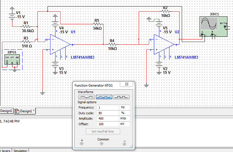
Summer+inverter op amp[multisim diagram]

  • Thread starter Thread starter bos1234
  • Start date Start date
  • Tags Tags
    Diagram
bos1234
Messages
26
Reaction score
0
I have the circuit below which is supposed to take input of 100mV to 400mV and output a voltage of -10v and 10V respectively. I have designed the circuit below through multisim and would like to verify if its correct before trying to connect on breadboard. When I simulate the circuit, I get 14.50V for dc and for AC i get 0V ?
29eqgp3.png
 
Engineering news on Phys.org
Without analyzing it in detail two big problems stand out.

1. I don't use "multisim" but it looks to me that you're unintentionally short circuiting those two points connected to channel A on the scope.

2. You have no negative power supplies! If you take a DC supply and connect the nominal positive side to ground but then give the supply a negative value (-15), then it's actually a positive supply (by virtue of double negative).
 
uart said:
1. I don't use "multisim" but it looks to me that you're unintentionally short circuiting those two points connected to channel A on the scope.
An oscilloscope has high input impedance.

In addition to what uart said about the supplies, don't ground the negative end of the function generator.
 
Jiggy-Ninja said:
An oscilloscope has high input impedance.

In addition to what uart said about the supplies, don't ground the negative end of the function generator.

I'm getting confused here. Where should the - terminal of oscilloscope and function generator be connected to?

The results of the simulation are shown below. Keep in mind I am supposed to get -10V and 10V

dc
vgsgtd.png


AC
11uasew.png
 
Last edited:
bos1234 said:
I'm getting confused here. Where should the - terminal of oscilloscope and function generator be connected to?

The results of the simulation are shown below. Keep in mind I am supposed to get -10V and 10V
The scope is fine. The - terminla of the function generator shouldn't be connected to anything.
 
Jiggy-Ninja said:
An oscilloscope has high input impedance.

Ha I know that. :smile:
That circuit diagram was a bit small on my monitor and I thought the scope had single ended inputs (with respect to ground). So that the two input wires would have been connected together to a common node at the oscilloscope input instead of to separate "+" and "-" nodes. I had to look a bit closer to notice that it's a differential input (+,-).
 
Last edited:
bos1234 said:
I'm getting confused here. Where should the - terminal of oscilloscope and function generator be connected to?
You've currently got the scope negative connected to the opamp negative input, which should be a "virtual earth" (if your circuit was working properly). Whether or not it will make a difference in multisim, in real life you shouldn't be adding extra capacitance and perhaps extra noise pickup here. You should connect it directly to a zero volt point (earth) instead.
 

Similar threads

  • · Replies 26 ·
Replies
26
Views
4K
  • · Replies 4 ·
Replies
4
Views
2K
  • · Replies 14 ·
Replies
14
Views
3K
Replies
9
Views
8K
Replies
2
Views
2K
  • · Replies 6 ·
Replies
6
Views
3K
  • · Replies 6 ·
Replies
6
Views
3K
  • · Replies 3 ·
Replies
3
Views
3K
  • · Replies 10 ·
Replies
10
Views
3K
  • · Replies 6 ·
Replies
6
Views
6K