Trouble building a Buck Converter

Click For Summary

Discussion Overview

The discussion revolves around the challenges of building a buck converter using the LT1170 integrated circuit (IC) to convert input voltages ranging from 25-50V to a stable output of 5V. Participants explore circuit design issues, component selection, and simulation results, with a focus on understanding the functionality of various components and the suitability of the LT1170 for this application.

Discussion Character

  • Technical explanation
  • Debate/contested
  • Experimental/applied

Main Points Raised

  • One participant describes their attempt to use the LT1170 for a buck converter, noting issues with achieving the desired output voltage and uncertainty about component functions.
  • Another participant suggests that the circuit may be wired incorrectly and requests a link to the datasheet for clarification.
  • Some participants express confusion about the LT1170's application in a buck configuration, questioning its appropriateness compared to more modern alternatives.
  • Concerns are raised about the minimum load requirement specified in the datasheet, with one participant asking if this condition is being met.
  • Several participants highlight the age of the LT1170 and suggest that it may not be the best choice for new designs, recommending more modern ICs instead.
  • Specific capacitor values are identified as critical for the circuit's operation, with one participant providing detailed recommendations for adjustments based on the schematic from the datasheet.
  • A participant mentions the importance of using LTspice for simulation and suggests that the original poster should optimize their design using the software.
  • Another participant emphasizes the need for multiple prototypes in switching power supply design to ensure reliability.
  • A request for assistance in designing a different buck converter for a specific application (Nvidia AGX Orin) is made, indicating ongoing interest in buck converter designs.

Areas of Agreement / Disagreement

There is no consensus on the suitability of the LT1170 for the buck converter application, with some participants advocating for its use while others recommend alternative, more modern ICs. The discussion includes multiple competing views regarding component selection and circuit configuration.

Contextual Notes

Participants note that the LT1170 is an older IC not specifically designed for buck configurations, which may lead to complications in achieving the desired output. There are also unresolved questions about the correct values for certain components and the impact of load conditions on circuit performance.

Who May Find This Useful

Electronics enthusiasts, engineers designing power supply circuits, and individuals interested in the practical application of buck converters may find this discussion relevant.

manoj1996
Messages
5
Reaction score
0
sodoyle said:
TL;DR Summary: I am trying to change from 25-50 Vin to 5 Vout

Hi, I am trying to use an LT1170 to convert between 25-50 Vin to 5 Vout. Actually, I would like to keep a constant 5 V out regardless of the input. To do that I know the input would have to be 5 V plus any voltage drops with a 100% duty cycle but it's going to be low current so large duty cycles aren't really an issue (I don't think).

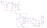
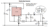
I made an LTspice model using the LT1170 from the built in library. I connected everything the same way as shown in the datasheet for a "positive buck converter" but do not get 5 V out. I will mention that a few differences I have are the zener diode and output resistor. Their circuit doesn't define the output resistor since it should regulate the voltage but will just output a higher current. I used 1 Ohm to make things simple. I'm not sure what voltage the zener diode should be rated for because I'm not really sure what it's even doing.

I understand if I can't really get help with LTspice here but even just getting help understanding what the components from the schematic do would be really helpful. Listing all of the components, there is what I think. I tried listing these starting at the left of the circuit and moving right in the order of top to bottom.C5 -- input capacitor to save the source from hard switching.
D3 -- not sure
C3 -- not sure
D1 -- normal buck converter diode (I'm not sure why they show a zener diode though).
C1 -- not sure
R2 -- not sure
R1 -- not sure
C2 -- not sure
D2 -- not sure
L1 -- normal buck converter output filter inductor
C4 -- normal buck converter output filter capacitor
R Unidentified below R4 -- Normal buck converter load resistor
R4 -- not sure

I've attached a screenshot of my LTspice schematic and the output current and voltage waveform at "out" and through "Rload". The link to the datasheet is below. I've also attached a screenshot from page 15 of the "positive buck converter" that I'm trying to build.

https://www.analog.com/media/en/technical-documentation/data-sheets/117012fi.pdf
Hii i have design PCB Board and i have solder components i have given input Vin=32V and Vout= 12V but i am getting Vout= 29V. Please check any changes in my schematic.
 

Attachments

  • schematic.pdf.png
    schematic.pdf.png
    15.8 KB · Views: 193
Engineering news on Phys.org
Welcome to PF.

At a quick glance, it looks to be wired incorrectly (and is drawn in a very confusing way). Can you give a link to the datasheet for that part that shows a typical application circuit? Thanks.
 
Wow, that's a weird part. I still haven't quite understood how it's used for a Buck configuration, but they do show a couple Buck applications in the datasheet:

https://www.analog.com/media/en/technical-documentation/data-sheets/117012fi.pdf

Is there a reason you want to use that part for a Buck converter? It seems like a more traditional part that is meant specifically for Buck converters would be a lot easier to use.
 
manoj1996 said:
Hii i have design PCB Board and i have solder components i have given input Vin=32V and Vout= 12V but i am getting Vout= 29V. Please check any changes in my schematic.
Maybe you could download LTspice from the AD website.
Then experiment with the LT1170 macromodel test fixture provided.
Then model your LT1170 positive buck circuit.
Once you have optimised the simulation, compare that to the hardware.
 
The example in the datasheet has a 100mA minimum load requirement. Are you providing that?

berkeman said:
It seems like a more traditional part that is meant specifically for Buck converters would be a lot easier to use.
Yep. Totally agree. This isn't a great choice IMO. Try searching TI for "simple switcher" for example.
 
berkeman said:
Wow, that's a weird part. I still haven't quite understood how it's used for a Buck configuration
It's a really old part designed for grounded switch topologies like boost and flyback. It's claim to fame was easy to use, had a big transistor, and tolerant of high(ish) voltages. Really not intended for high side switching. They would do better now to take those examples out of the data sheet and tell you to choose a different one. But back in the day, when there weren't so many of these ICs, it may have made more sense.

One of my prejudices is that anytime I see an IC intended to be grounded but applied in a floating (virtual ground) configuration, I assume it's a bad choice and look for something else.
 
  • Informative
Likes   Reactions: berkeman
How time flies.
The LT1170 dates from over 30 years ago.
Back then, for a low component count with an integrated switch, the competition was the LM78S40.
 
berkeman said:
Welcome to PF.

At a quick glance, it looks to be wired incorrectly (and is drawn in a very confusing way). Can you give a link to the datasheet for that part that shows a typical application circuit? Thanks.
 

Attachments

i have design circuit by datasheet in my schematic diagram
 

Attachments

  • Screenshot 2023-03-03 090003.png
    Screenshot 2023-03-03 090003.png
    10.3 KB · Views: 151
  • #10
I have put the "positive buck convertor" schematic, from the LT1170 datasheet, into LTspice, with the LT1170 model provided by LT with LTspice.

It does oscillate, but it does not regulate to 5 volt out.

It is sensitive to many components, but still does not regulate, it just fails to regulate in many different ways.

I am not surprised that your hardware fails to work. I suspect there is an error in the schematic. Some time will be needed to research the design, to get to the bottom of this.
 
  • Like
Likes   Reactions: berkeman
  • #11
Baluncore said:
Some time will be needed to research the design, to get to the bottom of this.
I'm not sure it's worth us investing all that time. As has been mentioned, this is a very old IC that was not really meant to be used in Buck topology.

@manoj1996 -- Can you use a more modern IC instead? Trying to use this old IC will likely take you 2-3 times as much effort and time as just using a simple switcher or other modern Buck topology IC.
 
  • Like
Likes   Reactions: artis
  • #12
I believe the problem is with the capacitor values you have used in the prototype.
Three capacitor values are critical to either starting, running, or both.
Your capacitors are numbered differently to those in the schematic provided in the data sheet.
Your C2 = 6.8uF needs to be 2.2uF
Your C4 = 0.1uF needs to be 1.0uF
Your C5 = 0.1uF needs to be 1.0uF
C1, C3 and C6 are OK.
You need a resistive load of between 2R and 50R, you do not have that.
The output voltage will be +5.12 volts, not 12 volts as you show. To change the output voltage from +5V to +12V, change only the value of your R6 from 3k74 to 10k75.
 
  • #13
Baluncore said:
I believe the problem is with the capacitor values you have used in the prototype.
Three capacitor values are critical to either starting, running, or both.
Your capacitors are numbered differently to those in the schematic provided in the data sheet.
Your C2 = 6.8uF needs to be 2.2uF
Your C4 = 0.1uF needs to be 1.0uF
Your C5 = 0.1uF needs to be 1.0uF
C1, C3 and C6 are OK.
You need a resistive load of between 2R and 50R, you do not have that.
The output voltage will be +5.12 volts, not 12 volts as you show. To change the output voltage from +5V to +12V, change only the value of your R6 from 3k74 to 10k75.
Thank you I will replace and i will update
 
  • #14
I need help That i am designing 5A to 10A DC Buck Converter for Nvidia AGX Orin Can please help which is suitable IC'S in that way i will design.
 
  • #15
It is a false economy to design and build one switching power supply. Like cars, you must build several of each prototype design, and crash test those to prove it is reliable.

The essential tool needed when designing switching supplies is LTspice. If you want help, you must get that software. There are many different software models and test jigs that come with LTspice.

Get your free copy of LTspice.
Attached is my LTspice model for your LT1170 buck converter.

LTspice.asc files are text, but need a .txt extension to attach to a post.
To run it on LTspice, change the extension from filename.asc.txt to filename.asc
 

Attachments

Similar threads

  • · Replies 10 ·
Replies
10
Views
3K
  • · Replies 14 ·
Replies
14
Views
2K
  • · Replies 13 ·
Replies
13
Views
3K
  • · Replies 32 ·
2
Replies
32
Views
6K
  • · Replies 10 ·
Replies
10
Views
2K
Replies
4
Views
3K
  • · Replies 27 ·
Replies
27
Views
6K
  • · Replies 14 ·
Replies
14
Views
7K
  • · Replies 10 ·
Replies
10
Views
6K
Replies
8
Views
2K