Voltage and current calculation of circuit

Join the discussion
Ask a follow-up here, or get your own question answered by working scientists, mathematicians and engineers — people, not an autocomplete.
Real named experts · corrections over time · the nuance an AI answer skips
5 replies · 2K views
PhysicsTest
Messages
260
Reaction score
27
Homework Statement
Need to calculate the voltage and current for a circuit
Relevant Equations
KCL and KVL equations , V=IR
I am trying to find voltages and currents of the below circuit,

3.3 -22000*I2 - 2200(I2-I3) = 0
3.3 -24200*I2 + 2200*I3 = 0 -> eq1

-(10 - I3)*1500 - (I2 - I3)*2200 = 0
-15000 + 1500*I3 - 2200*I2 + 2200*I3=0
-15000 - 2200*I2 + 3700*I3=0 -> eq2

Solving equations 1 and 2 i get I2=0.38 Amps and I3 = 4.28 Amps
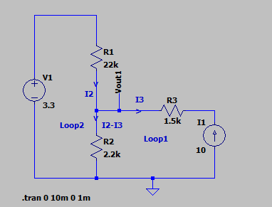
1674367119007.png


I assume i have completely gone wrong in calculations, can current I3 flow into the source. Please help.
 

Attachments

Physics news on Phys.org
If current 10 Amps flows through R3 then the voltage at vout1 shall be 1.5K*10 Volts = 15K volts, but if i see the simulation results it shows 20K Volts
1674369421048.png

It is all confusion.
 
Replace your .Transient analysis with a .DC operating point analysis. That will give you the voltages at all nodes and the currents in all components.

You may have to turn a passive component around to get that loop current flowing with the correct sign in the .DC report.

The arrow on the current source is conventional current. Your I3 arrow is in the opposite direction, which makes visualisation of the current flow more difficult.

You can replace R3 with a short circuit because it is in series with a current source.
 
Baluncore said:
You can replace R3 with a short circuit because it is in series with a current source.
This helped me to solve the problem
The updated circuit is
1674376709746.png

3.3 - 22000*I2 -2200*(10+I2) = 0
solving I2 = -0.90 Amps
Vout1=20K Volts it matches with the simulation results
--- Operating Point ---

V(n001): 3.3 voltage
V(vout1): 20000.3 voltage
I(I1): 10 device_current
I(R2): 9.09105 device_current
I(R1): -0.908955 device_current
I(V1): 0.908955 device_current

Still my question is why do i need to remove R3 to get result?
 
PhysicsTest said:
If current 10 Amps flows through R3 then the voltage at vout1 shall be 1.5K*10 Volts = 15K volts, but if i see the simulation results it shows 20K Volts
I think you were assuming the voltage across the current source was zero.
You were looking at the 10 amp through the 1k5 when it actually flows through the Thevenin resistance of Vout.

Another way to analyse it:
Node(2) has Thevenin resistance; Rth = (22k//2k2) = 2k000
3.3V * 2k2 / ( 22k + 2k2 ) = +0.300 volt;
Then add the (10A * 2k000) = 2000V;
To get node(Vout1), V(out) = +2000.300 V.
 
Reply
  • Like
Likes   Reactions: PhysicsTest
If you would change your sign for loop2 like Baluncore wrote, I think you would arrive at the solution. The current source being in the positive direction.

(10-I3)*1500 + (I2-I3)*2200=0