anhnha
- 179
- 1
I am wondering why LC tank only oscillates at resonant frequency not other frequencies?
Is there a physics explanation for that?
Is there a physics explanation for that?
Yes. If you write down the equation for the current and voltage, you get a second-order differential equation with the resonant frequency as the solution (see https://en.wikipedia.org/wiki/LC_circuit for the explanation of the derivation).anhnha said:I am wondering why LC tank only oscillates at resonant frequency not other frequencies?
Is there a physics explanation for that?
anhnha said:I am wondering why LC tank only oscillates at resonant frequency not other frequencies?
Jarrodmccarthy said:I'm not familiar with the symbols but they might be transistors.
Oscillation - it is possible. It looks like a Flip-Flop with tuned drain circuits to me. Since the LC combination has no phase shift at resonance, it does not help any. What helps, is that the MOSFET that is "on" only has a given amount of current (current source at the bottom of the figure) and after some time the current through the inductance does not increase and the voltage across it will decrease. This will make the other MOSFET start conducting, sending a current through its drain circuit and "stealing " current from the first MOSFET. This behavior will "kick" the drain circuit into oscillation mode and couple this oscillation to the other MOSFET.anhnha said:So, could you explain why this cross coupled oscillator below oscillate? It is only connected with a DC voltage source.
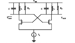
I guessed they were transistors so thanks for specifying MOSFE.Vanadium 50 said:They're MOSFETs. And circuits with transistors are not simple LC circuits.
Svein said:Oscillation - it is possible. It looks like a Flip-Flop with tuned drain circuits to me. Since the LC combination has no phase shift at resonance, it does not help any. What helps, is that the MOSFET that is "on" only has a given amount of current (current source at the bottom of the figure) and after some time the current through the inductance does not increase and the voltage across it will decrease. This will make the other MOSFET start conducting, sending a current through its drain circuit and "stealing " current from the first MOSFET. This behavior will "kick" the drain circuit into oscillation mode and couple this oscillation to the other MOSFET.
There are several variants of LC tank oscillator, and this is not one of the most used. The dominant circuits are the Colpitts oscillator (https://en.wikipedia.org/wiki/Colpitts_oscillator) and the Hartley oscillator (https://en.wikipedia.org/wiki/Hartley_oscillator).
I think those resistances are different so there would be a potential difference giving preference to one MOSFET or the other.anhnha said:Thanks for the detailed answer.
I have some problems understanding the oscillator. The first one relating to the boldfaced part above. I don't get what you meant here.
Second problem is that how can the oscillation start up? Two transistors are exactly the same, so which one will be ON first? Will both transistors be OFF permanently?
Hi, the resistances are same (not exactly because tolerance)Jarrodmccarthy said:I think those resistances are different so there would be a potential difference giving preference to one MOSFET or the other.
If both start OFF, they will not draw current, which makes the drain HIGH, turning the other one ON. If both start ON, they will pull the drain low, turning the other one OFF. Which one? Random.anhnha said:Second problem is that how can the oscillation start up? Two transistors are exactly the same, so which one will be ON first? Will both transistors be OFF permanently?
As I remarked above:anhnha said:I simulated the oscillator. If Vdd is step voltage then the oscillator oscillates but if Vdd is constant then it doesn't oscillate. Could you explain why?
Such a circuit will usually only oscillate when you do not want it to (cf. Murphy's law). Try this circuit instead:Svein said:It looks like a Flip-Flop with tuned drain circuits to me.
