- #1
freddie_mclair
- 43
- 2
- TL;DR Summary
- After being a beam is bent, due to the springback effect, the resulting bent radius is larger than the bending radius. How can I estimate the residual stress that remains in the beam after an elasto-plastic loading/bending?
Hello everyone, I hope you can give me hand with what I will present.
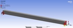
I have a beam with cross-section shown below.

I considered a simple linear hardening model for predicting the stress and strain developed by bending the beam on the radius ##R_0## around the y-axis, where:
The strain, ##\varepsilon_L(x)##, can be defined as:
##\varepsilon_L(x) = \frac{x}{R_0}##
And the stress, ##\sigma_L(x)##, developed in the beam due to the loading by bending is:
##\sigma_L(x) = \begin{cases}
\frac{x}{R_0} \cdot E \mbox{, if } x \leq \varepsilon_y \cdot R_0\\
\sigma_L(x) = S_y+(\frac{x}{R_0}-\varepsilon_y)\cdot E_1\mbox{, if } x \gt \varepsilon_y \cdot R_0
\end{cases}##
Where and ##\varepsilon_y = \frac{S_y}{E}##, ##S_y## is the yield strength and ##E## the Young's Modulus.
##E_1## is the tangent modulus which is defined as shown in the picture below.

I also know that, due to the springback effect, the relationship between the bending radius ##R_0## and the resulting radius ##R_r## is given by:
##\frac{1}{R_0} - \frac{1}{R_r} = \frac{M_b}{EJ}##
Where ##M_b## is the bending moment and ##J## the moment of inertia (in this case ##J=\frac{h^4}{12}-\pi \frac{r^4}{4}##).
The bending moment can be estimated by:
##M_b=2\int_0^{h/2} \sigma_L(x) b(x) x dx##
Where ##b(x)\cdot x## is the cross-sectional area of the beam and ##b(x)## is defined by:
##b(x) = \begin{cases}
h-2\sqrt{r^2-x^2} \mbox{, if } x \leq r\\
h \mbox{, if } x \gt r
\end{cases}##
Now, with all this at hand, how can I estimate the residual stress on the beam after bending, i.e., after unloading the beam?
Thanks in advance!
I have a beam with cross-section shown below.
I considered a simple linear hardening model for predicting the stress and strain developed by bending the beam on the radius ##R_0## around the y-axis, where:
The strain, ##\varepsilon_L(x)##, can be defined as:
##\varepsilon_L(x) = \frac{x}{R_0}##
And the stress, ##\sigma_L(x)##, developed in the beam due to the loading by bending is:
##\sigma_L(x) = \begin{cases}
\frac{x}{R_0} \cdot E \mbox{, if } x \leq \varepsilon_y \cdot R_0\\
\sigma_L(x) = S_y+(\frac{x}{R_0}-\varepsilon_y)\cdot E_1\mbox{, if } x \gt \varepsilon_y \cdot R_0
\end{cases}##
Where and ##\varepsilon_y = \frac{S_y}{E}##, ##S_y## is the yield strength and ##E## the Young's Modulus.
##E_1## is the tangent modulus which is defined as shown in the picture below.
I also know that, due to the springback effect, the relationship between the bending radius ##R_0## and the resulting radius ##R_r## is given by:
##\frac{1}{R_0} - \frac{1}{R_r} = \frac{M_b}{EJ}##
Where ##M_b## is the bending moment and ##J## the moment of inertia (in this case ##J=\frac{h^4}{12}-\pi \frac{r^4}{4}##).
The bending moment can be estimated by:
##M_b=2\int_0^{h/2} \sigma_L(x) b(x) x dx##
Where ##b(x)\cdot x## is the cross-sectional area of the beam and ##b(x)## is defined by:
##b(x) = \begin{cases}
h-2\sqrt{r^2-x^2} \mbox{, if } x \leq r\\
h \mbox{, if } x \gt r
\end{cases}##
Now, with all this at hand, how can I estimate the residual stress on the beam after bending, i.e., after unloading the beam?
Thanks in advance!