- #1
kirkmcg97
- 5
- 0
- TL;DR Summary
- I've designed a subsea pumped storage hydro system and want to know if I'm on the right track with my flow rate and head loss calculations
I've created a concept design of a subsea pumped hydro storage system, and need to use the flow rate in order to calculate power output. I can calculate the energy storage capacity using ##E = mgh##:
$$E = mgh = 25675000×9.81×200 = 50374 MJ = \frac {50374MJ}{3600} = 13992 kWh$$
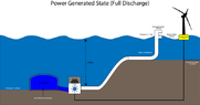
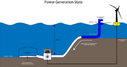
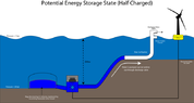
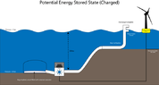
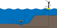
I've attempted to determine the flow rate by choosing a turbine (5MW Francis from https://www.researchgate.net/publication/302969536_The_use_of_LINGO_programming_language_to_develop_a_computer_tool_to_provide_a_technical_and_economic_analysis_of_a_hydraulic_potential_that_allows_the_application_of_Francis_turbines_and_Kaplan_turbin/figures?lo=1) and working backwards, to then find the resulting pipe diameter and head loss. In the model below, the top of the pipe has a valve that will open to let seawater in during the power generation stage (high energy demand), down through a 90/10 Cu/Ni pipe, through a turbine and subsequently fill up the vessel, which is located 200 m below the inlet (Head = 200 m). Vessel design doesn't take into account the pressure at this depth through use of a bag seen here. In times of low demand, using excess energy produced from the wind turbine, the water will be pumped back up to the surface to be stored as potential energy.
So in generator mode, the rated discharge will be:
$$P_g=\rho \times g \times h \times \eta_g \times Q_g$$
Rearranging for Q while assuming generator efficiency is 0.9 gives:
$$Q_g = \frac{P_g}{\rho \times g \times h \times \eta_g} = 2.7599m^3/s$$
(Can generate rated capacity for 5.03 hours)
Rearranging the formula for pump mode to find Qp;
$$Q_p = \frac{P_g \times \eta_p}{\rho \times g \times h \times} = 2.2355m^3/s$$
(Can be operated for 6 hours)
Assuming pump velocity (vp) to be 5m/s, required diameter (d) is found using:
$$A=\frac{Q}{v}$$ then $$ A=\pi \times \frac{d^2}{4}$$ therefore d = 0.754m.
Reynolds Number:
$$Re = \frac{u \times d_h}{v} = 362500$$
So flow is turbulent.
Reading from Moody chart and using Colebrook equation to check, friction coefficient (f) = 0.0147.
Therefore via Darcy Weisbach, Pressure Loss = 399 kPa and Head Loss = 39m.
Have I done this correctly or is there something glaringly obvious that I've missed? Any thoughts or suggestions are welcome! And please note this doesn't (and probably won't) be economically feasible, it's purely a concept to see if something like this could work.
$$E = mgh = 25675000×9.81×200 = 50374 MJ = \frac {50374MJ}{3600} = 13992 kWh$$
I've attempted to determine the flow rate by choosing a turbine (5MW Francis from https://www.researchgate.net/publication/302969536_The_use_of_LINGO_programming_language_to_develop_a_computer_tool_to_provide_a_technical_and_economic_analysis_of_a_hydraulic_potential_that_allows_the_application_of_Francis_turbines_and_Kaplan_turbin/figures?lo=1) and working backwards, to then find the resulting pipe diameter and head loss. In the model below, the top of the pipe has a valve that will open to let seawater in during the power generation stage (high energy demand), down through a 90/10 Cu/Ni pipe, through a turbine and subsequently fill up the vessel, which is located 200 m below the inlet (Head = 200 m). Vessel design doesn't take into account the pressure at this depth through use of a bag seen here. In times of low demand, using excess energy produced from the wind turbine, the water will be pumped back up to the surface to be stored as potential energy.
- Head = 200 m
- Pipe Length = 1594m (assuming a straight path between elevations)
- Vessel Volume = 25,000 m3
- Seawater Density = 1027 kg/m3
- Turbine Power = 5MW
- Generator Efficiency (##\eta_g##) = 0.9
So in generator mode, the rated discharge will be:
$$P_g=\rho \times g \times h \times \eta_g \times Q_g$$
Rearranging for Q while assuming generator efficiency is 0.9 gives:
$$Q_g = \frac{P_g}{\rho \times g \times h \times \eta_g} = 2.7599m^3/s$$
(Can generate rated capacity for 5.03 hours)
Rearranging the formula for pump mode to find Qp;
$$Q_p = \frac{P_g \times \eta_p}{\rho \times g \times h \times} = 2.2355m^3/s$$
(Can be operated for 6 hours)
Assuming pump velocity (vp) to be 5m/s, required diameter (d) is found using:
$$A=\frac{Q}{v}$$ then $$ A=\pi \times \frac{d^2}{4}$$ therefore d = 0.754m.
Reynolds Number:
$$Re = \frac{u \times d_h}{v} = 362500$$
So flow is turbulent.
Reading from Moody chart and using Colebrook equation to check, friction coefficient (f) = 0.0147.
Therefore via Darcy Weisbach, Pressure Loss = 399 kPa and Head Loss = 39m.
Have I done this correctly or is there something glaringly obvious that I've missed? Any thoughts or suggestions are welcome! And please note this doesn't (and probably won't) be economically feasible, it's purely a concept to see if something like this could work.
Attachments
Last edited: