Heat pump efficiency calculations - Compressor power issue

In summary: I'm sorry, I don't understand what you are asking.In summary, the heat pump comprises of the 4 components: evaporator, compressor, condenser, and expansion valve.The thermal power required to heat the building: 12.1 kW at condensing temperature tc = 44.3 deg CFor the evaporator: vaporizing temperature tv = -7 deg CSubcooling temperature for the heat pump Δ tsc = 5 deg Cadiabatic coefficient: k = 1.16vaporising pressure: pv =t(tv) =paspiration =4barcondensing pressure: pc = t(tc) = pdischarge =17barvapor density: ρv=17.0 kg/
  • #1
Martin Harris
103
6
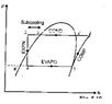
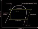
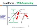
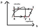
The heat pump comprises of the 4 components: evaporator, compressor, condenser and expansion valve.

Thermal power required to heat the building: 12.1 kW at condensing temperature tc = 44.3 deg C
For the evaporator: vaporizing temperature tv = -7 deg C
Subcooling temperature for the heat pump Δ tsc = 5 deg C
adiabatic coefficient: k = 1.16
vaporising pressure: pv =t(tv) =paspiration =4bar
condensing pressure: pc = t(tc) = pdischarge =17bar
vapor density: ρv=17.0 kg/m3
specific volume for aspiration vaspiration = 1/ρv = 1/17kg/m3 = 0.058823529 m3/kg
internal compressor efficiency: ηi=0.84
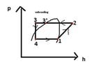
h1= hv(tv) = 402.56 kJ/kg
h3 =hl(tsc,pc) =248.6 kJ/kg

Now I tried finding out the following:
a)Thermal power Q0 at the evaporator
b)Compressor power
c)efficiency of the heat pump (both COP and refrigeration cycle efficiency ε )

a)Q0=q0*mrf, where q0 = specific heat load, and mrf=mass floware for the refrigerant

q0 = h1-h4 = h1-h3; because h3=h4
so q0 = 402.56 kJ/kg - 248.6 kJ/kg => q0 = 153.96kJ/kg

compressor work: compressor_work = (k/((k-1)*ηi))*paspiration*vaspiration*((pdischarge/paspiration)^((k-1)/k)-1)*100
compressor_work = 44.85735668 kJ/kg

enthaply in the 2nd point: h2 = h1+compressor_work = 402.56 kJ/kg+44.85735668 kJ/kg
h2 = 447.4173567 kJ/kg

specific heat load at the condenser: qc = h2-h3 = 447.4173567 kJ/kg - 248.6 kJ/kg
qc =198.8173567 kJ/kg

so: mrf = Qc/qc = 12.1 kW/198.8173567 kJ/kg
mrf = 0.060859878 kg/s (refrigerant mass flowrate)

Thermal power Q0 at the evaporator: Q0=q0*mrf
Q0 = 153.96kJ/kg*0.060859878 kg/s
Q0 = 9.369986761 kW

b)Compressor_power = (mass_flowrate_refrigerant * compressor_work) / (ηmotor*ηelectrical)
Problem arises here because I was given just the internal efficiency ηi=0.84, but the formula uses the efficiency of the motor ηmotor and the electrical efficiency ηelectrical...so how can I calculate this? (as I don't have the ηmotor*ηelectrical), I don't want to guess though...

c)COP =qc/work_compressor = 198.8173567 kJ/kg / 44.85735668 kJ/kg
COP = 4.432
ε = heat load evaporator/work done = COP - 1 = 3.432

What do you think of the calculations, do they make any sense? I'd really appreciate a peer review.

My actual question is, how can I calculate the compressor power at b) as I don't have those 2 efficiencies (ηmotor and ηelectrical), but just the ηi which is the internal efficiency of the compressor?
 
Engineering news on Phys.org
  • #2
Martin Harris said:
My actual question is, how can I calculate the compressor power at b) as I don't have those 2 efficiencies (ηmotor and ηelectrical), but just the ηi which is the internal efficiency of the compressor?
I don't have time to check the calcs right now, but based on what was given, they are probably asking for the mechanical power, not electrical.
 
  • Like
Likes Martin Harris and Lnewqban
  • #3
Hi,
Thanks for the reply, I was given just the actual internal efficiency for the compressor.
Is there any way to calulate the compressor power with just the data I have, without having mechanical and electrical efficiencies?
 
  • #4
Please find below a schematic diagram if it is of any help.
The heat exchangers have plates and are using water and refrigerant.
 

Attachments

  • Schematic Diagram.jpg
    Schematic Diagram.jpg
    29.8 KB · Views: 177
Last edited:
  • #5
This pertains to the work done on the working fluid in the compressor.

If I use the isentropic equations for k = 1.16, I get a temperature of 52.4 C exiting the compressor and an enthalpy increase of 37.7 kJ/kg in the compressor. If I use the thermodynamic tables for R22, I get a temperature of 67.9 C exiting the compressor and an enthalpy increase of 36.5 kJ/kg in the compressor. So, either way, the work done on the refrigerant is about 37 kJ/kg in the compressor. Assuming an isentropic efficiency of 0.84, doing it the first way, I confirm your value of 44.8 kJ/kg for the enthalpy change and the work.

I also confirm your determination of the mass flow rate.
 
  • Like
Likes russ_watters
  • #6
Regarding the power, efficiency, and COP, I agree with @russ_watters interpretation.
 
  • Like
Likes Martin Harris and russ_watters
  • #7
Thank you!
All right, in this case, how can those be calculated then with the data I was given? I have my attempt in post#1, but still can't do the compressor power because I don't have the motor and electrical efficiencies, just the internal compressor efficiency which was used to calculate the work for the compressor.
 
Last edited:
  • #8
The compressor power is the specific enthalpy change of the compressor times the mass flow rate, right?
 
  • Like
Likes Martin Harris
  • #9
Hi,
Right, okay. So can we say that compressor power = mass flowrate of refrigerant * specific work for the compressor?
 
  • #10
If I'm asked to plot a log p-h diagram for the following statement:

"A building needs a thermal power for heating Q = 12 [kW] at with a condensing temperature tc = 44.3 deg C, the heating being performed with heat pump. The heat source is represented by the soil. The installation works with a refrigerant whose vaporization temperature is tvap = -7 deg C. The degree of subcooling of the installation ΔtSC = 5 deg C."

So for this case on the log p-h diagram I should plot just the sub-cooling part, right? I wasn't told anything about superheating.

The question is...can we have sub-cooling without super-heating though?
So should I plot just the sub-cooling process on the log p-h diagram? Or should I plot both sub-cooling and superheating on the log p-h diagram?

Should the log p-h diagram be like Fig.1 or like Fig.2? (please see below)
 

Attachments

  • Fig1.png
    Fig1.png
    2.2 KB · Views: 139
  • Fig2.jpg
    Fig2.jpg
    48.9 KB · Views: 137
Last edited:
  • #11
I would like to see the p-H diagram for your coolant.
 
  • Like
Likes Martin Harris
  • #12
Hi, thanks for the quick reply, I do appreciate it.

The problem is that I have to plot the p-h diagram for the heat pump myself, but not sure if I should have just the subcooling process since I was given just the subcooling degree "It is known that the degree of subcooling of the heat pump ΔtSC = 5 deg C."

Or should I have both sub-cooling and super-heating, though the word superheating was not specified within the text...that got me confused, is it possible to have just subcooling without superheating for the heat pump?

"A building needs a thermal power for heating Q = 12 [kW] at with a condensing temperature tc = 44.3 deg C, the heating being performed with heat pump. The heat source is represented by the soil. The installation works with a refrigerant whose vaporization temperature is tvap = -7 deg C. The degree of subcooling of the heat pump is known such as ΔtSC = 5 deg C."

Don't know if to plot the p-h diagram just with the sub-cooling or with both sub-cooling and superheating, based on the text provided above.

Anyway, for the coolant (R22) I assume the log p-h diagram is something like this:
1619113237312.png
 
Last edited:
  • Like
Likes Chestermiller
  • #13
I found a P-H diagram. In my judgment, the correct diagram should be Fig 1. Although they don't say there is superheating, its seems obvious that the vapor exiting the compressor should be superheated at 17 bars. Just follow an isentrop upward from a saturated vapor at 4 bars.
 
  • Like
Likes Martin Harris
  • #14
Thank you for your logical response.

I've been given some additional data:

internal efficiency for the compressor: 0.84

pv(vaporizing pressure) = t(tv) = 4bar

pc(condensing pressure)=t(tc)=17 bar

ρv=17 kg/m3

h1=hv(tv)=402.56 kJ/kg, where tv = vaporizing temperature, yet it doesn't say anything about tsh (superheating temperature)

h3=h1(tsc,pc)=248.6 kJ/kg, where tsc=subcooling temperature, pc=condensing pressure

k=1.16 (adiabatic index)

Yet again, superheating is not specified, so I guess, it's just subcooling, right?
 
Last edited:
  • #15
Martin Harris said:
Thank you for your logical response.

I've been given some additional data:

internal efficiency for the compressor: 0.84

pv(vaporizing pressure) = t(tv) = 4bar

pc(condensing pressure)=t(tc)=17 bar

ρv=17 kg/m3

h1=hv(tv)=402.56 kJ/kg, where tv = vaporizing temperature, yet it doesn't say anything about tsh (superheating temperature)

h3=h1(tsc,pc)=248.6 kJ/kg, where tsc=subcooling temperature, pc=condensing pressure

k=1.16 (adiabatic index)

Yet again, superheating is not specified, so I guess, it's just subcooling, right?
When you compress the saturated vapor that enters the compressor, the vapor is compressed isentropically and exits the compressor in a superheated state at 17 bars and about 70 C. So it enters the condenser superheated and exits sub-cooled.
 
  • Like
Likes Martin Harris
  • #16
khodournajem said:
Dear All ,
how can i post a new question
regards
Go to the forum you are interested in posting to, and click on the button POST THREAD.
 
  • Like
Likes Martin Harris and khodournajem
  • #17
Chestermiller said:
When you compress the saturated vapor that enters the compressor, the vapor is compressed isentropically and exits the compressor in a superheated state at 17 bars and about 70 C. So it enters the condenser superheated and exits sub-cooled.
Right, okay. So, now with the actual given data if I'm asked to plot a log p-h diagram for the entire heat pump, it should resemble the one like in Fig.1, right? Just the subcooling part basically, because superheating (before entering the compressor 1-1') was not stated anywhere within the text. When I am speaking about superheating I am referring to the one before entering the compressor. I currently don't know based on the provided data if the p-h diagram should include the superheated process right before entering the compressor, given that the input data (text) hasn't specified anything about superheating.

So how should the log p-h diagram look like for the heat pump?
 
Last edited:
  • #18
I would assume it is saturated vapor before entering the compressor. It exits the compressor as a superheated vapor at 17 bars and on the order of 70 C. This is consistent with your Fig.1. So it enters the condenser as a superheated vapor and exits as a sub cooled liquid.
 
  • Like
Likes Martin Harris
  • #19
Hi

Thanks for your reply.
Like I should not have superheated process 1-1' before entering the compressor.

I am trying to understand why I was not given any information on purpose regarding the superheated process before entering the compressor.

So, the p-g diagram, should look something like this, right? (please see below)
 

Attachments

  • Fig3.jpg
    Fig3.jpg
    45 KB · Views: 146
  • Fig4.jpg
    Fig4.jpg
    16.2 KB · Views: 137
Last edited:
  • #20
Martin Harris said:
Hi

Thanks for your reply.
Like I should not have superheated process 1-1' before entering the compressor.

I am trying to understand why I was not given any information on purpose regarding the superheated process before entering the compressor.

So, the p-g diagram, should look something like this, right? (please see below)
I don't know what 1-1' means. But, in any case, Fig. 4, not Fig. 3
 
  • Like
Likes Martin Harris
  • #21
Hi,

Thanks for the reply.

Please see Fig.5 and Fig.6 below, where 1->2 compressor, 2->3 condenser, 3->4 expansion valve, 4->1 evaporator.

Which one would you say that is now the correct p-h diagram for the above given data for the heat pump?
 

Attachments

  • Fig5.JPG
    Fig5.JPG
    7.8 KB · Views: 133
  • Fig6.JPG
    Fig6.JPG
    16.7 KB · Views: 136
  • #22
Martin Harris said:
Hi,

Thanks for the reply.

Please see Fig.5 and Fig.6 below, where 1->2 compressor, 2->3 condenser, 3->4 expansion valve, 4->1 evaporator.

Which one would you say that is now the correct p-h diagram for the above given data for the heat pump?
Figure 5
 
  • Like
Likes Martin Harris
  • #23
Thank you for your quick reply, really much appreciated!

Yeah right, absolutely, it makes sense to enter as saturated vapor in the compressor, yet I am afraid that if it won't be superheated the compressor might corrode due to liquid droplets, but then again, I was not told anything about superheated vapors.
 
  • #24
Can we say that the efficiency for the refrigeration cycle for the heat pump = COP -1 ?

I know that usually the refrigeration cycle efficiency = Qevaporator/Work done by compressor
 

1. How is the efficiency of a heat pump calculated?

The efficiency of a heat pump is calculated by dividing the heat output by the energy input. This is expressed as a ratio, typically ranging from 1 to 5, with higher numbers indicating a more efficient heat pump.

2. What factors affect the efficiency of a heat pump?

The efficiency of a heat pump can be affected by several factors, including the outside air temperature, the size and quality of the heat pump, and the insulation and air flow in the building it is heating or cooling.

3. What is the compressor power issue in heat pump efficiency calculations?

The compressor power issue refers to the amount of energy required to run the compressor in a heat pump. This is an important factor in efficiency calculations, as a more powerful compressor will consume more energy and potentially decrease the overall efficiency of the heat pump.

4. How can the compressor power issue be addressed in heat pump efficiency calculations?

To address the compressor power issue, it is important to select a heat pump with a properly sized and efficient compressor. Regular maintenance and cleaning of the heat pump can also help to improve its efficiency and reduce the amount of energy needed to run the compressor.

5. What is a good efficiency rating for a heat pump?

The efficiency rating of a heat pump can vary depending on the type and size of the unit, as well as the climate and building it is being used in. Generally, a heat pump with an efficiency ratio of 3 or higher is considered to be a good rating.

Similar threads

  • Materials and Chemical Engineering
Replies
10
Views
2K
  • Engineering and Comp Sci Homework Help
Replies
1
Views
520
Replies
8
Views
555
Replies
3
Views
2K
  • Engineering and Comp Sci Homework Help
Replies
10
Views
1K
  • Thermodynamics
Replies
6
Views
1K
  • Engineering and Comp Sci Homework Help
Replies
1
Views
2K
  • Mechanical Engineering
Replies
1
Views
1K
  • Mechanical Engineering
2
Replies
40
Views
3K
  • Engineering and Comp Sci Homework Help
Replies
2
Views
3K
Back
Top