- #1
Saut Renato
- 4
- 1
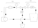
I'm building a fertigation system using 1 inch venturi injector with ball valve at the end to simulate drip irrigation system pressure requirement. i have read to start an injection you need 30% pressure difference between injector inlet and outlet. the pressure I'm simulating is around 10 meter head meaning it need 13 meter head at the injector inlet. currently I'm producing less than 4 meter head at the inlet. I'm still confused how does venturi injector work especially at predicting operating pressure at the inlet given certain pump curve. Is it the pump that is inadequate or should i just change to a smaller injector? this is the setup i'm currently using:

This is the curve of the pump I'm using, its a 125 watt output pump

this is the performance spec of the injector:

edit:
i have installed pressure gauge next to the pump and it reads 0.5 bar or around 5 meter head. according to pump curve the pump should give a flow rate of 30.5 L/min. I have calculated the loss from the 1.4 meter 1 inch pipe and it gives around 0.07 meter head loss (absolute roughness 0.0015). So why would the pump operate at 5 meter head if the loss from the pipe only 0.07 meter? i'm guessing it's because the contraction at the venturi but when i calculate the loss coefficient (Kl) it gives a 0.72 value (from cengels fluid dynamics book gradual contraction with an angle of 60 degrees have Kl of 0.07). So where do i miss?
This is the curve of the pump I'm using, its a 125 watt output pump
this is the performance spec of the injector:
edit:
i have installed pressure gauge next to the pump and it reads 0.5 bar or around 5 meter head. according to pump curve the pump should give a flow rate of 30.5 L/min. I have calculated the loss from the 1.4 meter 1 inch pipe and it gives around 0.07 meter head loss (absolute roughness 0.0015). So why would the pump operate at 5 meter head if the loss from the pipe only 0.07 meter? i'm guessing it's because the contraction at the venturi but when i calculate the loss coefficient (Kl) it gives a 0.72 value (from cengels fluid dynamics book gradual contraction with an angle of 60 degrees have Kl of 0.07). So where do i miss?
Attachments
Last edited: