Kinematic diagram of a gear mechanism

In summary, the mechanism attached below is designed to rotate an LED by increasing the rotation speed of the ring gear. The ring gear is the input and the rest of the components (sun gear, planet gear, ring gear and sprocket for the belt) should increase their speed until the engine starts that led of about 15 lumens.
  • #1
Pawllentiew
11
1
Thread moved from the technical forums, so no Homework Template is shown
Can anyone help me with a kinematic analysis for the mechanism attached below? I need the outline of the mechanism, its notes and the necessary formulas to find out the transmission ratio and the rest of the values.
 

Attachments

  • Gear mechanism.pdf
    248.8 KB · Views: 299
Physics news on Phys.org
  • #2
Welcome to PF. We require that you show your best efforts to work on the problem before we can offer tutorial help. How are you going to approach this problem? :smile:
 
  • #3
I looked at some tutorials and read the basic information to make a kinematic diagram. but all were based on a simple system with only 2-4 gears placed in series. I did not find an example to understand in which the ring gear rotates 3 planet gears. and how I could calculate that in the way they are placed in my example
 
  • #4
Pawllentiew said:
I looked at some tutorials and read the basic information to make a kinematic diagram. but all were based on a simple system with only 2-4 gears placed in series. I did not find an example to understand in which the ring gear rotates 3 planet gears. and how I could calculate that in the way they are placed in my example

Hi, you may want to look up 'planetary gear' or 'epicyclic gears' as these types of questions are more involved than standard gear train questions. These build on the same principles, but the solution methods themselves tend to fall into two main categories (at least in the problems I have seen):
1. Thinking of the problem as a superposition between rotating with the carrier and relative frames
2. Thinking about velocity profiles across the gears

I don't think it makes sense to fully type out the methods here due to time constraints, but these methods may help in finding those ratios (but you need to know a few numbers: either the radii or teeth numbers for a few of the gears)
 
  • Like
Likes berkeman
  • #5
I'll look over what you mentioned. thanks a lot. but if someone could make a quick sketch of what the kinematic diagram should look like it would help me tremendously
 
  • #6
Pawllentiew said:
I'll look over what you mentioned. thanks a lot. but if someone could make a quick sketch of what the kinematic diagram should look like it would help me tremendously
That would be doing part of your homework for you, which we are not allowed to do. Post what you find, and we can use that as a place to start refining the discussion. Thank you @Master1022 for the helpful info. :smile:
 
  • Like
Likes Master1022
  • #7
I understand. I will come back with what I found and what I did
 
  • Like
Likes berkeman
  • #8
Pawllentiew said:
Can anyone help me with a kinematic analysis for the mechanism attached below? I need the outline of the mechanism, its notes and the necessary formulas to find out the transmission ratio and the rest of the values.
Please, see:
https://en.m.wikipedia.org/wiki/Epicyclic_gearing

Note that there is a reduction of rotational speed among the Sun and the planet gears.
 
Last edited:
  • #9
Hi, I've been pretty busy for the last few weeks but I've managed to make a scheme. I'm not good at this. It's the first time I've received something like this to do. so it's probably wrong. That's why I need some clarification if anyone offers to give it to me.

I don't know how to start the calculations for this mechanism. Should I calculate the number of teeth? How do I do this if I don't have the mechanism and I'm just trying to create it from scratch? Do I randomly put the number of teeth or do I have to follow a formula? What is that formula for this mechanism?

After finding out the number of teeth how should I create the formulas to find out the torque for my mechanism? do I break down the mechanism in the part that contains sun gear, planet gear, ring gear and the part that contains the sprocket for the belt and the belt? Do I calculate them when they are decomposed or do they have to be calculated together to find out the torsion or the rest of the parameters? And what would be the formula that emerges in any case?

I really don't know how I should start and where to start. a few formulas would help me answer these questions. This mechanism aims to increase the rotation enough to rotate the dc motor at a speed high enough (1600 rpm) to turn on an LED. Basically, a rope is glued to a ring gear to which a weight and a counterweight are attached. Gravity helping the mechanism to rotate, ring gear is the input. From this ring gear the rest of the components should increase their speed until the engine starts that led of about 15 lumens. I know that for this LED it takes 1600rpm to start with the engine.

How do I find the required initial speed with which the ring gear must rotate when the weight is falling. I'm very stuck because I don't know what to start with and what are the formulas needed for this kind of mechanism with just this information I have. I only own what the mechanism looks like as a drawing. but without number of teeth or other dimensions
 

Attachments

  • Untitled-1.png
    Untitled-1.png
    22.5 KB · Views: 151
Last edited by a moderator:
  • #10
Pawllentiew said:
This mechanism aims to increase the rotation enough to rotate the dc motor at a speed high enough (1600 rpm) to turn on an LED.
The output shaft must turn at 1600 RPM, but how much power is needed by the LED. What is the operating voltage and current of the LED ?
Then you can work your way backwards to the suspended mass, calculating the reducing speed and increasing torque through the system of gears.
 
  • #11
Baluncore said:
The output shaft must turn at 1600 RPM, but how much power is needed by the LED. What is the operating voltage and current of the LED ?
Then you can work your way backwards to the suspended mass, calculating the reducing speed and increasing torque through the system of gears.
I have the specifications of the product for which I am trying to recreate the mechanism. Gravity light 2
 

Attachments

  • GL02-Specifications.png
    GL02-Specifications.png
    58.4 KB · Views: 135
  • #12
Now you must read the specifications and answer the question.
How much power is needed by the LED ?
 
  • #13
I think 0.1 W
 
  • #14
Pawllentiew said:
I think 0.1 W
Why? How did you calculate that? Or did you find it in a datasheet? (link?)
 
  • #15
their first product I know worked with 0.1 W at maximum power. I assumed that this product is the same
 

Attachments

  • GravityLight-GL01-Specifications.png
    GravityLight-GL01-Specifications.png
    32.7 KB · Views: 125
  • #16
Hi, I need a little help with this problem with compound planetary gears. I don't know how to apply the formulas for this specific type of placement.

I need to know the final speed of the engine knowing the number of teeth z1 = -104 ring gear which is internal, z2,3,4 = 22 for small planets, z5,6,7 = 65 for large planets, z8 = 17 for the small sun, z9 = 95 for the big sun and z10 = 13 for spool gear.

A weight of 12kg will be attached to the ring gear on one side and 2kg of counterweight on the other from a height of 2 m. I want to calculate the speed and torque that the engine will have if I want the weight to fall within 20 minutes from the 2m.

And i also need the ratio that the system have. The modulus of the wheels is 0.8 and the pressure angle is 20. I also know that the spool from the z10 have diameter equal to 30 mm and the one from the motor have 15 mm. These are the data I know and don't really know how to apply it. Can someone help me?
 

Attachments

  • Untitled-1.png
    Untitled-1.png
    21.4 KB · Views: 105
  • #17
Item (1) in the drawing is yellow. I assume that is the internal-cut ring-gear with 104 teeth.
Will the string be wound around the outside of the yellow drum?
What is that outer drum diameter?

You refer to an engine and to a motor. Is that actually a generator being driven by the weights on the string, or will the motor drive the drum against the string in the style of a Proney Brake?
https://en.wikipedia.org/wiki/Prony_brake
 
  • #18
Yes. that is the inner one of 104 teeth. and the diameter of the drum is 20 mm. I mean the version in which weight drive the motor
 
  • #19
The manufacturer is Deciwatt, website:https://deciwatt.global/support/gl02

Click on the Inventors Pack button. Slides #5 and 6 show internals. There is not a planetary gear train, just some internal tooth gears for added strength. Oops, guess I missed post #16.
Some Theory of Operatiion is also provided on the slides.

Have Fun!

Cheers,
Tom
 
Last edited:

1. What is a kinematic diagram of a gear mechanism?

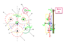
A kinematic diagram of a gear mechanism is a simplified representation of a gear system that shows the relative motion and connections between all the gears in the system.

2. How is a kinematic diagram of a gear mechanism different from a schematic diagram?

A kinematic diagram focuses on the motion and connections between gears, while a schematic diagram shows the electrical or mechanical components of a system.

3. What information can be obtained from a kinematic diagram?

A kinematic diagram can provide information on the gear ratio, direction of rotation, and speed of the gears in a system.

4. How is a kinematic diagram useful in engineering and design?

A kinematic diagram allows engineers to visualize and analyze the motion and connections of gears in a system, which is crucial for designing and optimizing gear mechanisms for various applications.

5. Can a kinematic diagram be used to predict the performance of a gear system?

Yes, a kinematic diagram can be used to calculate the output speed and torque of a gear system, which can help predict its performance and identify potential issues.

Similar threads

  • Engineering and Comp Sci Homework Help
Replies
6
Views
897
  • Engineering and Comp Sci Homework Help
Replies
3
Views
1K
  • Engineering and Comp Sci Homework Help
Replies
9
Views
1K
  • Engineering and Comp Sci Homework Help
Replies
10
Views
1K
  • Engineering and Comp Sci Homework Help
Replies
3
Views
786
  • Engineering and Comp Sci Homework Help
Replies
8
Views
1K
  • Mechanical Engineering
Replies
5
Views
2K
  • Engineering and Comp Sci Homework Help
Replies
6
Views
2K
Replies
4
Views
986
  • Engineering and Comp Sci Homework Help
Replies
3
Views
2K
Back
Top