- #1
ARoyC
- 56
- 11
Is there any way to measure the capacitance of a capacitor indirectly using a multimeter that does not have the option to measure capacitance directly?
You mean uF, right?ARoyC said:The capacitance range is from about 1microohm to 4000microohm.
The input resistance of your DVM will be in parallel with the capacitor voltage that you are measuring, so will tend to discharge the cap more than with just an external resistance. If your DVM has 1MegOhm input impedance and you are using kiloOhm resistors in your circuit, then it will not cause much error. But for smaller values of capacitance, you will need to use larger values of resistance to get discharge/charge behaviors that you can observe on human timescales, so the DVM input resistance may become a factor in your RC time constant calculations.ARoyC said:Sorry, I did not understand your second question.
You will need to include a switch in your circuit, and open or close it to measure the discharge or charging time constant. The resistor goes in a different place for each one of those test circuits.ARoyC said:Then I can use a stopwatch to measure the time required for the voltage drop across the capacitor to become half of the EMF.

Interesting! That will limit the range of capacitances that can be measured, but it's a great simplification.Baluncore said:You could avoid external circuitry by charging the cap with a resistance measurement, then measuring the rate the voltage falls during a voltage measurement.
BTW, I hope this is not a misplaced homework assignment in the EE forum, because we have solved it for you multiple times over. If it is a homework problem, at least give attribution to this thread in your solution that you send to your class.ARoyC said:Is there any way to measure the capacitance of a capacitor indirectly using a multimeter that does not have the option to measure capacitance directly?
Well, I did that way back in mF range for finding functional caps for motherboards (amongst disassembled caps from motherboards).Baluncore said:You could avoid external circuitry by charging the cap with a resistance measurement, then measuring the rate the voltage falls during a voltage measurement.
")
One other tip -- see if you can put your DVM into "Range Hold" mode so that it does not try to autorange during the measurement of the increasing or decreasing voltage values. If it keeps changing ranges during the voltage changes, that will slow down the measurements. Also, some DVMs have a bargraph displat at the bottom of the LCD, which is handy when trying to see the changing voltage intuitively.ARoyC said:I can construct a circuit using a battery, a thin wire, a resistor and a capacitor. I can calculate the EMF of the battery and the resistance using the multimeter. Then I can use a stopwatch to measure the time required for the voltage drop across the capacitor to become half of the EMF.
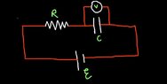
Sorry for being so late. I was loaded with college assignments. I am attaching the circuit diagram. Please forgive my disastrous drawing.berkeman said:Yes, it would be good to see a sketch of the circuit that you have in mind.
The resistor would go in different places depending on whether you are measuring the discharge time or the charging time. If you are measuring the time it takes to charge the cap up, you would connect these in series: Battery, switch, resistor, capacitor. You close the switch and measure the time to reach 63% (or whatever percentage you want to use for your RC formula) of the battery voltage.
If you want to measure discharge time, you would connect the resistor and cap in parallel, and then connect those to the battery through the switch. You would close the switch and let the cap charge up (relatively quickly, depending on the output resistance of the battery), and then open the switch and measure the time it takes to fall to 37% (or whatever) of the battery voltage.
If you want to get fancy, you could figure out how to use a single pole double throw (break before make) switch to be able to measure both the charge and discharge times...
Could you please explain a bit, if possible?Baluncore said:You could avoid external circuitry by charging the cap with a resistance measurement, then measuring the rate the voltage falls during a voltage measurement.
That works for measuring the charging time constant if you put a SPST switch to the left of the battery.ARoyC said:I am attaching the circuit diagram. Please forgive my disastrous drawing.
Those are really interesting methods. Thanks for the insight.hutchphd said:Two other ways come to mind.
But the method of directly finding the decay time with known resistance is probably easiest and best for your 10% target accuracy. Of course if you really wanted accuracy there are null bridge methods and oscillator frequency methods
- If you have some known capacitors you can use a battery to charge one of them to battery V and then connect it to the unknown cap and then measure the resultant voltage.
- If you have (or can make) a constant current supply then the increase in capacitor voltage will be linear in time. The constant slope of V vs t will give you C pretty accurately
Actually, this is not a homework problem. But another homework problem inspired me to think about this.berkeman said:BTW, I hope this is not a misplaced homework assignment in the EE forum, because we have solved it for you multiple times over. If it is a homework problem, at least give attribution to this thread in your solution that you send to your class.
I am not sure that I could understand this. Could you please explain?Baluncore said:A good linesman with a moving coil ohmmeter, would measure the resistance of a twisted pair line that was open circuit. Judging by the “kick”, how close the pointer got to zero ohms and how quickly it fell back towards infinity, they could judge the length of the cable. It would tell them roughly how far to go when searching for a break in a line.
In effect that was a dynamic capacitance measurement, a measurement that would once have been done in a lab with a ballistic galvanometer.
Okay, I will look into this.berkeman said:One other tip -- see if you can put your DVM into "Range Hold" mode so that it does not try to autorange during the measurement of the increasing or decreasing voltage values. If it keeps changing ranges during the voltage changes, that will slow down the measurements. Also, some DVMs have a bargraph displat at the bottom of the LCD, which is handy when trying to see the changing voltage intuitively.
ARoyC said:Actually, this is not a homework problem. But another homework problem inspired me to think about this.
berkeman said:That works for measuring the charging time constant if you put a SPST switch to the left of the battery.
Yes, sorry. I have to add a switch. Then by calculating the time constant, won't it be possible to calculate the capacitance?berkeman said:That works for measuring the charging time constant if you put a SPST switch to the left of the battery.
Do I have to do the discharge to recheck my calculated value?berkeman said:And for a circuit like I described using a SPDT switch (break-before-make) to alternately measure the charge and discharge times, you could use something like this (with better R and C values, and you don't need the Ammeter so just short it out):
View attachment 294843
https://rsdacademy.net/textbooks/dcelectronics/Part5/CapacitorDemonstrationCircuit.png
You need to fully discharge the capacitor before you measure the charging time constant waveform. And similarly, you need to fully charge the cap before you measure the discharge time constant waveform.ARoyC said:Do I have to do the discharge to recheck my calculated value?
Why won't the capacitor start at 0V and V_batt if I discharge it fully?berkeman said:You need to fully discharge the capacitor before you measure the charging time constant waveform. And similarly, you need to fully charge the cap before you measure the discharge time constant waveform.
Alternately, you need to use the starting voltage for either one in your calculation, and not just assume the capacitor starts at 0V and Vbatt for the two transients. Does that make sense?
I don't understand the question. In the circuit you posted, if you put a switch in series with the battery, the first time you close the switch you will be able to measure the charging time constant. But disconnecting the SPST switch does nothing to discharge the cap, so unless you have some other way to discharge the cap (like the SPDT circuit), you only get to do the experiment once.ARoyC said:Why won't the capacitor start at 0V and V_batt if I discharge it fully?
Yes, that I understand. I need to construct the circuit in such a way so that I can discharge it. And the SPDT circuit is needed for it. Probably I asked the last question due to a misunderstanding.berkeman said:I don't understand the question. In the circuit you posted, if you put a switch in series with the battery, the first time you close the switch you will be able to measure the charging time constant. But disconnecting the SPST switch does nothing to discharge the cap, so unless you have some other way to discharge the cap (like the SPDT circuit), you only get to do the experiment once.
So are you going to put it together and see what values of C (using what values of R?) you can measure pretty accurately? That's the fun part of the project...ARoyC said:Thank you so much for the solution!
You will need to experiment with a multimeter and some capacitors.ARoyC said:Could you please explain a bit, if possible?
Capacitance is the ability of a material to store an electrical charge. It is important to measure because it helps determine the efficiency and performance of electronic components.
A basic multimeter is a handheld device used to measure electrical properties such as voltage, current, and resistance. To measure capacitance, the multimeter sends a small known current through the capacitor and measures the time it takes for the capacitor to charge up to a certain voltage. The capacitance value is then calculated using this time and the known current.
The unit of capacitance is farads (F), but it is often represented in microfarads (µF) or picofarads (pF) for smaller values. On a multimeter, the capacitance unit is usually represented by the letter "C" or the symbol for farads (F).
Yes, most multimeters have the ability to measure capacitance in both AC and DC circuits. However, it is important to select the correct setting on the multimeter depending on the type of circuit being measured.
The accuracy of capacitance measurements using a basic multimeter can vary depending on the quality of the multimeter and the type of capacitor being measured. Generally, multimeters have an accuracy of around 1-5% for capacitance measurements.