Nodal Analysis of a circuit with 3 sources and 3 resistors

In summary, the conversation discusses a circuit problem involving voltage sources and resistors. One person points out a potential typo in the problem and suggests that the solution relies on a specific trick. They also mention the importance of learning general solutions rather than relying on tricks. The conversation then moves on to discussing a specific case where the trick may not work and how to approach it. The conversation ends with the suggestion of solving the problem for oneself to stay mentally sharp.
  • #1
Xiao Xiao
30
3
Homework Statement
Determine the current i2 as labeled in the circuit with the assistance of Nodal Analysis.
Relevant Equations
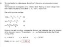
V1=(Vc-Vb), V3=(Vc-Va)
--> 0.0(Vc-Vb)+(Vc-Va)/5=(Va-Vb)/3
--> (Va-Vb) /3+10=(Vb-Vc)/2
--> 0.02(Vc-Va)+(Vb-Vc)/2=(Vc-Va)/5

No solution for the system of equations.
Are my equations wrong or is soemthing incorrect in the Question itself, because it has 10V on a current source.
Screenshot_20220103_135401.jpg
 
Physics news on Phys.org
  • #2
Can you say which elements are a, b and c.
 
  • #3
tech99 said:
Can you say which elements are a, b and c.
Oh yes, starting from left, first node is Va, second is Vb, third is Vc.
 
  • #4
That must be a 10V voltage source, since the "V" isn't defined otherwise.

Also, some of your equations are incorrect, I think.
 
  • #5
DaveE said:
That must be a 10V voltage source, since the "V" isn't defined otherwise.

Also, some of your equations are incorrect, I think.
Yeah, I guess I was tired when I wrote them and didn't copy some stuff correctly.

I got my hands on the solution manual and their equations are the same as me, except they didn't include 0.2*V3. But they considered 10V as 10A. I'll just send it to my professor and ask.
 
  • #6
Look carefully at KCL at the left most node. The current source ##0.2v_3 = \frac{v_3}{5} = i_2## that means there is no current through the ##2 \ohm## resistor, and no current in the right most source. The problem is trivial given these specific component values.
 
  • #7
DaveE said:
Look carefully at KCL at the left most node. The current source ##0.2v_3 = \frac{v_3}{5} = i_2## that means there is no current through the ##2 \ohm## resistor, and no current in the right most source. The problem is trivial given these specific component values.
Ooooh, yes you're right, I completely missed that, thank you.
 
  • #8
Not my favorite HW problem.

First, IMO, there's a typo. Which is really bad in HW problems, legal contracts, resumes, etc. Other places, like your PhD dissertation or your NYT editorial, not so much. Students lack the experience and confidence to say that the question is wrong, they think they are wrong, they get confused instead of educated, and waste a lot of time.

Second, the easy solution relies on noticing a particular trick; a special case. Much better to learn general solutions than special tricks that only work rarely. This is especially important when you are being paid to design circuits and the problem is often to choose component values, not just analyse what someone else chose.
 
  • Like
Likes Xiao Xiao
  • #9
DaveE said:
Look carefully at KCL at the left most node. The current source ##0.2v_3 = \frac{v_3}{5} = i_2## that means there is no current through the ##2 \ohm## resistor, and no current in the right most source. The problem is trivial given these specific component values.
You mean the right most node, don't you?

What if the 5 ohm resistor is 4 ohms? Then your trick doesn't work. What would be the solution of the circuit in case the 5 ohm resistor is 4 ohms?
 
  • #10
The Electrician said:
You mean the right most node, don't you?
Oops! No, I meant the leftmost source ##0.02v_1 = 0 ##, since ##v_1=0## . This is because the rightmost source equals the current across the top.

The Electrician said:
What if the 5 ohm resistor is 4 ohms? Then your trick doesn't work.
Yes, exactly, that's why I wouldn't choose this as a HW problem. It's not great learning for working in the real world, where tricks rarely work this well.

The Electrician said:
What would be the solution of the circuit in case the 5 ohm resistor is 4 ohms?
Are you asking me to solve this for you? You first; then I'll help if you get stuck.

You can start by telling me what the middle source is, voltage or current? You may notice I didn't actually finish the original problem.
 
  • Like
Likes BvU
  • #11
DaveE said:
Oops! No, I meant the leftmost source ##0.02v_1 = 0 ##, since ##v_1=0## . This is because the rightmost source equals the current across the top.Yes, exactly, that's why I wouldn't choose this as a HW problem. It's not great learning for working in the real world, where tricks rarely work this well.Are you asking me to solve this for you? You first; then I'll help if you get stuck.

You can start by telling me what the middle source is, voltage or current? You may notice I didn't actually finish the original problem.
The middle source has to be a voltage because if it's a current source there would be 3 current sources feeding a floating object (3 resistors in a delta configuration) from which there is no return path to ground, and the voltage of that object would be indeterminate. If the middle source is a voltage source, then at least the voltage(s) of the floating object won't be indeterminate.

Of course I'm not asking you to solve it for me. Solve it for yourself; I know you, like me, solve problems like this to keep in good (mental) shape.

And we want the TS to be able to solve it.
 
  • Like
Likes BvU and DaveE
  • #12
The Electrician said:
The middle source has to be a voltage because if it's a current source there would be 3 current sources feeding a floating object (3 resistors in a delta configuration) from which there is no return path to ground, and the voltage of that object would be indeterminate. If the middle source is a voltage source, then at least the voltage(s) of the floating object won't be indeterminate.
Yes. Although since they only asked about ##i_2##, the question is solvable. It's a case of infinite vs. a single solution.

I have also been flippant about the typo. There are people (on the other side of the Atlantic) that draw their voltage sources exactly the same as their current sources. WHICH DRIVES ME CRAZY; I HATE IT, I HATE IT, I HATE IT! I pretend, as much as possible, that those people don't actually exist. Although they would tell you everything is in order here. Let's just celebrate that they don't draw their inductors like capacitors with a negative value.

The Electrician said:
I know you, like me, solve problems like this to keep in good (mental) shape.
Actually, no I don't. Perhaps I should. But I've done enough in the past and, honestly, it's a pretty rote application of network analysis. Something has to make me interested first, then I'll solve it, right up until the point that I lose interest. *

* PS: For this I can thank the antiquated EE department head where I did my MS. His thing was linear network analysis. He wrote a book and made it a requirement that every grad student take his class. It was a (nearly) complete waste of effort, I instantly forgot at least 90% of it. Great if your the guy that has to code the first SPICE algorithms, which had already been done long ago. He taught me to hate this stuff. I mean, how much time do you want to spend constructing and solving simple linear algebra problems? It's exactly contrary to the approach I learned as an undergrad; "design oriented analysis" as named by my guy, R.D. Middlebrook. Where the answer isn't as important as understanding why you get that answer.
 
Last edited:
  • Like
Likes BvU
  • #13
Xiao Xiao said:
Yeah, I guess I was tired when I wrote them and didn't copy some stuff correctly.

I got my hands on the solution manual and their equations are the same as me, except they didn't include 0.2*V3. But they considered 10V as 10A. I'll just send it to my professor and ask.
Xaio Xaio, DaveE showed you a trick that gets you the right answer, but the problem requires you to find the solution using nodal analysis. Your nodal equations have errors. Will you be working on this problem's nodal analysis any more?
 
  • #14
The Electrician said:
Xaio Xaio, DaveE showed you a trick that gets you the right answer, but the problem requires you to find the solution using nodal analysis. Your nodal equations have errors. Will you be working on this problem's nodal analysis any more?
Yes, these are my equations so far.
1. ##0.02v_1+i_2=(v_a-v_b)/3##
2. ##(v_a-v_b) /3+10=(v_b-v_c)/2##
3. ##(v_b-v_c)/2+i_2=i_2##

I do use this ##0.2v_3=i_2## and through equation 3 I find that ##v_b-v_c=v_1=0##
and solve the rest of the equation using that.
 
  • Like
Likes BvU
  • #15
Xiao Xiao said:
Yes, these are my equations so far.
1. ##0.02v_1+i_2=(v_a-v_b)/3##
2. ##(v_a-v_b) /3+10=(v_b-v_c)/2##
3. ##(v_b-v_c)/2+i_2=i_2##

I do use this ##0.2v_3=i_2## and through equation 3 I find that ##v_b-v_c=v_1=0##
and solve the rest of the equation using that.
Your 3rd equation doesn't look like a proper nodal equation. Can you write in the proper form? If you do, do they have a solution?

Did you find out if the middle source labeled 10V is supposed to be a current or voltage source?

Does the solution manual explain its solution?
 
  • #16
The Electrician said:
Your 3rd equation doesn't look like a proper nodal equation. Can you write in the proper form? If you do, do they have a solution?

Did you find out if the middle source labeled 10V is supposed to be a current or voltage source?

Does the solution manual explain its solution?
The third one should be ##(v_b-v_c)/2+0.2v_3=(v_c-v_a)/2##

##(v_c-v_a) /2= i_2## and ##0.2v_3=i_2##
That's why I wrote it that way. I solved it by hand and got an answer for it, but I'm not sure if it's correct. I couldn't find out if it's 10V or 10A but I decided to count is a current source, idk why I didn't ask the professor in the end.

The solution manual answer is weird, they put a resistor instead of the left current source, but didn't include it in the equations, I'll just attach it.
 

Attachments

  • Screenshot_20220103_222311.jpg
    Screenshot_20220103_222311.jpg
    39.4 KB · Views: 92
  • #17
So we have an exercise with a picture that has a current source ##0.2\, v_2## instead of a resistor of ##7\, \Omega## and a current source that says ##10 \,V## ? Anything else ?

##\ ##
 
  • #18
BvU said:
So we have an exercise with a picture that has a current source ##0.2\, v_2## instead of a resistor of ##7\, \Omega## and a current source that says ##10 \,V## ? Anything else ?

##\ ##
Nothing else
 
  • Like
Likes BvU
  • #19
The answer in the solution manual is totally messed up!

First of all, without some path to ground (which the 7 ohm resistor provides), the original problem from post #1 of this thread has no solution for the voltages at the nodes, although I suppose one could say that I2 = 0 anyway.

The addition of a 7 ohm resistor makes a solution possible, but the equations they show are incomplete; they haven't included the 7 ohm resistor in the equations! The equations they show have no solution so where did they get those numerical values? I have no idea. The third equation needs a term +Vc/7 at the end. If that is added, then we have a solution:

Messedup.png
 
  • #20
Xiao Xiao said:
The solution manual answer is weird, they put a resistor instead of the left current source, but didn't include it in the equations, I'll just attach it.
The resistor is in place of the right current source.
 
  • Like
Likes Xiao Xiao
  • #21
The Electrician said:
The answer in the solution manual is totally messed up!

First of all, without some path to ground (which the 7 ohm resistor provides), the original problem from post #1 of this thread has no solution for the voltages at the nodes, although I suppose one could say that I2 = 0 anyway.

The addition of a 7 ohm resistor makes a solution possible, but the equations they show are incomplete; they haven't included the 7 ohm resistor in the equations! The equations they show have no solution so where did they get those numerical values? I have no idea. The third equation needs a term +Vc/7 at the end. If that is added, then we have a solution:

View attachment 295151
Yeah it's completely messed up, and I couldn't figure on what basis they changed the question. So I'm sticking with the solution that I ended up with in my previous reply.

I did end up asking my professor about if there's an error in the Question or not but he hasn't responded yet.
 
  • #22
Xiao Xiao said:
Yeah it's completely messed up, and I couldn't figure on what basis they changed the question. So I'm sticking with the solution that I ended up with in my previous reply.

I did end up asking my professor about if there's an error in the Question or not but he hasn't responded yet.
Has your professor responded yet? What did he say?
 
  • #23
The Electrician said:
Has your professor responded yet? What did he say?
No he did not, unfortunately. So I asked him about the solution in hope he respond, if he uploads the solution for the question later (because this was in our assignment) or answers my question, I'll update with the righ question or method to use here.
 

1. How do I determine the nodal voltages in a circuit with 3 sources and 3 resistors?

To determine the nodal voltages in a circuit with 3 sources and 3 resistors, you can use Kirchhoff's Current Law (KCL) and Ohm's Law. First, label each node in the circuit. Then, write KCL equations for each node, setting the sum of currents entering the node equal to the sum of currents leaving the node. Finally, solve the resulting system of equations to find the nodal voltages.

2. Can I use nodal analysis for circuits with more than 3 sources and resistors?

Yes, nodal analysis can be used for circuits with any number of sources and resistors. However, the number of equations needed to solve the circuit will increase with the number of sources and resistors, making it more complex and time-consuming.

3. What are the advantages of using nodal analysis over other circuit analysis methods?

Nodal analysis is advantageous because it allows for the simultaneous analysis of multiple nodes in a circuit, making it useful for complex circuits with multiple sources and resistors. It also results in a set of linear equations, which can be easily solved using various techniques such as Gaussian elimination.

4. Are there any limitations to nodal analysis?

One limitation of nodal analysis is that it can only be used for circuits with a single reference node. Additionally, it may be more difficult to use for circuits with dependent sources or non-linear elements.

5. Can nodal analysis be used for AC circuits?

Yes, nodal analysis can be used for both DC and AC circuits. However, for AC circuits, the nodal voltages will be complex numbers, so the analysis will involve solving a system of complex equations.

Similar threads

  • Engineering and Comp Sci Homework Help
Replies
1
Views
255
  • Engineering and Comp Sci Homework Help
Replies
7
Views
907
  • Engineering and Comp Sci Homework Help
Replies
2
Views
1K
  • Engineering and Comp Sci Homework Help
Replies
2
Views
1K
  • Engineering and Comp Sci Homework Help
Replies
4
Views
3K
  • Engineering and Comp Sci Homework Help
Replies
4
Views
532
  • Engineering and Comp Sci Homework Help
Replies
1
Views
2K
  • Engineering and Comp Sci Homework Help
Replies
5
Views
2K
  • Engineering and Comp Sci Homework Help
Replies
2
Views
1K
  • Engineering and Comp Sci Homework Help
Replies
13
Views
277
Back
Top