OPamp circuit - how to simplify this term?

In summary, the conversation discusses the calculation of Uout/Uin in a circuit. The denominator is in a factored form and the numerator needs to be expanded and collected into a polynomial. The quadratic terms in s cannot be factored with real numbers, so they are left in a format like (as^2 + bs + 1). The roots of the quadratic are real when Q is less than or equal to 1/2 and the quadratic is factorable with real numbers. However, since the analysis is done using variables, the general solution is not factorable and is left as a quadratic.
  • #1
altruan23
22
5
Homework Statement
Calculate Uout/Uin
Relevant Equations
Basic op amp eq.
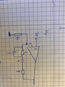
So this is the circuit.
1647795120099.png

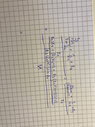
And here i tried to calculate Uout/ Uin , any suggestion how to simplify this term?? I used Uout= Uin * (1+ Z2/Z1)
1647795302938.png
 

Attachments

  • 1647795064355.png
    1647795064355.png
    91.3 KB · Views: 85
  • 1647795214408.png
    1647795214408.png
    85.2 KB · Views: 93
Physics news on Phys.org
  • #2
It looks good so far. The denominator is done; it's in a factored form. For the numerator, you need to expand it again and collect the terms for s into a polynomial. Usually the quadratic terms in s can't be factored (with real numbers); factor it if you can into ## (1+\frac{s}{\omega_0})(1+\frac{s}{\omega_1}) ##, but that never seems to workout. So, then you just leave them in a format like ## (as^2 + bs + 1) ## which we would actually express as ## ({(\frac{s}{\omega_0})}^2 + \frac{s}{Q \omega_0} +1) ## for reasons you'll get to when you study the quadratic response (simple harmonic oscillators and resonant circuits).
 
  • #3
DaveE said:
It looks good so far. The denominator is done; it's in a factored form. For the numerator, you need to expand it again and collect the terms for s into a polynomial. Usually the quadratic terms in s can't be factored (with real numbers); factor it if you can into ## (1+\frac{s}{\omega_0})(1+\frac{s}{\omega_1}) ##, but that never seems to workout. So, then you just leave them in a format like ## (as^2 + bs + 1) ## which we would actually express as ## ({(\frac{s}{\omega_0})}^2 + \frac{s}{Q \omega_0} +1) ## for reasons you'll get to when you study the quadratic response (simple harmonic oscillators and resonant circuits).
Note that for the quadratic term ## ({(\frac{s}{\omega_0})}^2 + \frac{s}{Q \omega_0} +1) ##, the roots (given by the quadratic formula) are real when ## Q \leq \frac{1}{2} ## and the quadratic is factorable with Reals. But, since your analysis is done (correctly, IMO) with variables (like R1, C2, etc.), we don't know what value Q has until we put in the values. So, the general solution isn't factorable, that's why we normally leave it as a quadratic.
 

What is an OPamp circuit?

An OPamp circuit is a type of electronic circuit that uses an operational amplifier (OPamp) to amplify or manipulate an input signal. It is commonly used in a variety of electronic devices such as audio amplifiers, filters, and voltage regulators.

How does an OPamp circuit work?

An OPamp circuit typically consists of an operational amplifier, resistors, and capacitors. The operational amplifier amplifies the difference between its two input terminals and outputs the result. The resistors and capacitors are used to set the gain and frequency response of the circuit.

What are the advantages of using an OPamp circuit?

OPamp circuits offer high gain, high input impedance, and low output impedance, making them ideal for amplification and signal processing. They also have a wide range of applications and can be easily integrated into electronic systems.

How do you simplify an OPamp circuit?

To simplify an OPamp circuit, you can use circuit analysis techniques such as Kirchhoff's laws and Ohm's law to determine the equivalent circuit. This involves replacing complex components with simpler ones while maintaining the same functionality.

What are some common applications of OPamp circuits?

OPamp circuits are commonly used in audio amplifiers, active filters, voltage regulators, and signal processing circuits. They are also used in instrumentation and control systems, as well as in communication systems such as modulators and demodulators.

Similar threads

  • Engineering and Comp Sci Homework Help
Replies
1
Views
1K
  • Engineering and Comp Sci Homework Help
Replies
21
Views
2K
  • Engineering and Comp Sci Homework Help
Replies
8
Views
1K
  • Engineering and Comp Sci Homework Help
Replies
8
Views
781
  • Engineering and Comp Sci Homework Help
Replies
34
Views
2K
  • Engineering and Comp Sci Homework Help
Replies
1
Views
1K
  • Engineering and Comp Sci Homework Help
Replies
0
Views
521
  • Engineering and Comp Sci Homework Help
Replies
8
Views
1K
  • Engineering and Comp Sci Homework Help
2
Replies
44
Views
3K
  • Engineering and Comp Sci Homework Help
Replies
2
Views
676
Back
Top