Solving Current & Power in 4 & 3 Wire Circuits

In summary: In the end I ran into something of a cul-de-sac where my expression for R was a quadratic with complex roots, so I must have gone awry somewhere. I'll check my workings before posting again to see if I can spot any mistakes....just a quick question, did you get exactly the same or equivalent expressions for current as I did, or were there any slight differences?
  • #1
Evari5te
8
4
Homework Statement
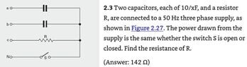
Two capacitors each of "10/xF" and a resistor are connected to a 50 Hz three phase power supply, as shown in figure 2.27. The power drawn from the supply is the same whether the switch S is open or closed. Find the resistance of R. - See attached file for diagram and original statement
Relevant Equations
Complex Power S = VI*
I assume that the "power drawn" refers to the active power, which I understand as being the real part of S in either scenario.

For power to be the same regardless of switch S being closed (four wire) or open (three wire)

Four wire power = three wire power

=>Re{VcnIc*} = Re{ [Vcn-Vnn’]Ic*}

Where Vcn is the c line to neutral voltage of the supply, Ic is the c line current and Vnn’ is the voltage of the load floating neutral with respect to ground in the three wire scenario.

Vnn’ is determined by Millman’s equation Vnn' = VanYa + VbnYb + VcnYc / (Ya + Yb + Yc)
where voltages are phase to neutral of the supply and Y values the admittances (reciprocal of impedance)
Ya = Yb = jωC = j2πfC
Yc = 1/R
My thoughts were I could use mesh current analysis to derive equations for current hence power in each case in terms of ωC and R, set the equations for real power equal to each other and solve for R. While ωC are known I opted to leave them as letters thinking this might make life easier when reducing the equations.

I assumed "10/xF" is actually 10 micro Farads - I have the Kindle version and am guessing that /x is a printing error because an unusual character, most likely μ, has been kicked out, n and p being the only other common prefixes.

I took Vab as the reference phasor and V(line) is 1 Volt. The actual voltage is irrelevant to the question

Four wire (switch closed):

Three mesh current loops with following voltages:
Vab = 1 + j0
Vbc = -0.5 -j0.866
Vcn = (0 + j)/√3

(2/jωC) x I1 - (1/jωC) x I2 + 0 x I3 = 1 + j0
Can be rearranged
2 x I1 - I2 = jωC (equation 1)
-1/jωC x I1 + (R + 1/jωC) x I2 - R x I3 = -0.5-j0.866 (equation 2)
-R x R2 + R x I3 = j/√3

Ia = I1
Ib = I2 - I1
Ic = I3 - I2

All the above resolved to give me Ic = j/√3R therefore Ic* = -j/√3R

S= VI* = VcnIc*

Vcn = VL/√3 x (0 + j) where VL was set = 1

S =(1/j√3) x -j/√3R
So S is entirely real and equal to 1/3R

Three wire (switch open)

Two mesh current loops with following voltages
Vab = 1 + j0
Vbc = -0.5 -j0.866

2 x I1 - I2 = jωC (eq. 1)
-I1 + I2(1 + jωCR) = ωC(0.866 – j0.5)

Ia = I1
Ib = I2 - I1
Ic = - I2

resolved to give me Ic = -√3ωC / (1 + j2ωCR)

I multiplied top and bottom by (1 - j2ωCR) to give me a complex numerator with real denominator,

Ic = (-√3ωC + j√3(2)ω^2C^2R) / (1 + 4ω^2C^2R^2)

so Ic* = (√3ωC - j√3(2)ω^2C^2R) / (1 + 4ω^2C^2R^2)

This was already starting to look pretty ugly.

By the time I had calculated Vnn' using Millman's equation and hence Vcn - Vnn' in order to proceed to complex power S = [Vcn - Vnn']Ic* things really got out hand - equations with R to the fourth power - giving me serious doubt as to whether I was missing a far easier, more obvious solution to this.....
 

Attachments

  • problem2_3.JPG
    problem2_3.JPG
    24.8 KB · Views: 55
Physics news on Phys.org
  • #2
How much current do you expect to flow through the switch when closed?
 
  • #3
In = Ia + Ib + Ic from the above equations this is the mesh current I3.

By my reckoning this is a current phasor as follows:

I3 = ωC(√3 - 2/√3) + j/(√3R)

Further simplifies to:

ωC/√3 [ (3-2) + j/R ] = [ωC/√3] [ 1 + j/R]
 
  • #4
What does "10/xF" mean?
 
  • #5
DaveE said:
What does "10/xF" mean?
That issue is mentioned in the OP. @Evari5te is assuming it means 10 μF .
 
  • Like
Likes DaveE
  • #6
Only the resistor consumes power. The power delivered for the two cases will be the same if the current amplitude through the resistor, ##|I_c|##, is the same for the two cases. Your results for the two cases are
$$I_c = \frac{j}{\sqrt 3 R} \,\,\,\, \rm{switch \,\, closed}$$ $$I_c = \frac{-\sqrt{3} \omega C}{1+j2\omega C R} \,\,\,\, \rm{switch \,\, open}$$

What do you get for ##R## by requiring ##|I_c|## to be the same for the two cases?

I don't follow the details of your work. I worked it a little differently but got similar equations for ##I_c## for the two cases.
 
  • Like
Likes scottdave
  • #7
TSny said:
Only the resistor consumes power. The power delivered for the two cases will be the same if the current amplitude through the resistor, ##|I_c|##, is the same for the two cases. Your results for the two cases are
$$I_c = \frac{j}{\sqrt 3 R} \,\,\,\, \rm{switch \,\, closed}$$ $$I_c = \frac{-\sqrt{3} \omega C}{1+j2\omega C R} \,\,\,\, \rm{switch \,\, open}$$

What do you get for ##R## by requiring ##|I_c|## to be the same for the two cases?

I don't follow the details of your work. I worked it a little differently but got similar equations for ##I_c## for the two cases.
Many thanks for the steer.

I had a go at resolving this by setting |Ic open| = |Ic closed|, where |Ic| = sqrt( real terms^2 + imag. imag^2). In the end I ran into something of a cul-de-sac where my expression for R was a quadratic with complex roots, so I must have gone awry somewhere. I'll check my workings before posting again to see if I can spot any mistakes....just a quick question, did you get exactly the same or equivalent expressions for current as I did, or were there any slight differences?
 
  • #8
Evari5te said:
Many thanks for the steer.

I had a go at resolving this by setting |Ic open| = |Ic closed|, where |Ic| = sqrt( real terms^2 + imag. imag^2). In the end I ran into something of a cul-de-sac where my expression for R was a quadratic with complex roots, so I must have gone awry somewhere. I'll check my workings before posting again to see if I can spot any mistakes....just a quick question, did you get exactly the same or equivalent expressions for current as I did, or were there any slight differences?
I got the same expressions for ##I_c^{\small \rm S \, closed}## and ##I_c^{\small \rm S \, open}## as yours except for an overall numerical factor (the same for each equation) that probably has to do with a different choice of normalization of the applied voltage. This overall factor cancels out when setting ##|I_c^{\small \rm S \, closed}| = |I_c^{\small \rm S \, open}|##. So, we should get the same result for ##R##. Thus, you have to solve $$\frac 1 {\sqrt 3 R} = \frac{\sqrt{3} \omega C}{|1 + j 2 \omega C R|}$$ for ##R##. Or, $${\sqrt{1 +4 \omega^2 C^2 R^2}} = 3 \omega C R.$$
 
  • Like
Likes Evari5te
  • #9
Finally had a bit of time to circle back to this problem and indeed I had gone some way adrift.

Thanks to TSny both for the steer and for using LaTex, which once I learnt to use it helped me with setting out my workings much more clearly and spotting the mistakes.

Also for the common sense learning points - I did not need to use current mesh analysis for the four wire scenario, it should have been obvious that with the zero impedance link connecting load and supply common points to earth the voltage across the resistor, ##\mathbf{V_R}## is the same as the phase c supply voltage ##\mathbf{V_{cn}}##.

It then follows from basic circuit theory with just a single resistor on phase c that ##I_c = \frac{V_{cn}}{R}## directly giving the expression for current,

##I^{S closed}_c = \frac{j}{\sqrt{3}R}##.

where ##\mathbf{V_{ab}}## is chosen as the reference phasor, so no need to solve three simulataneous equations that only served to show this fact.

Similarly in the three wire scenario it was only necessary to solve two simultaneous equations from the mesh current analysis to determine an expression for ##I^{S open}_c##.

The voltage across the resistor is - apart from not being relevant to the question once current is determined - given by basic circuit theory ##V_R = I^{S open}_c.R## so thinking I would need to use Macmillans formula to determine voltage of floating neutral ##V_{nn'}## was all an unnecessary distraction.

All this to say I was getting a bit too hung up on irrelevant - and in the end way too complicated formulas - to resolve, and TSny's insight that magnitude of phase c current was only thing needed to equate across both scenarios without fully working out power was really helpful.

Final workings to get the right answer shown below:

##I^{S closed}_c = \frac {j}{\sqrt{3}.R}## and ##I^{S open}_c = -\frac{\sqrt{3}ωC}{(1 + j2ωCR)}##

and for power to be the same in both scenarios, ##|I^{S closed}_c| = |I^{S open}_c|##

##I^{S closed}_c## is a vertical phasor with entirely imaginary component therefore

##|I^{S closed}_c| = \frac{1}{\sqrt{3}.R}##

##I^{S open}_c## is the product of ## -\sqrt{3}ωC.\frac{1}{(1 + j2ωCR)}##

therefore

##|I^{S open}_c| = \sqrt{3}ωC.\frac{1}{|1 + j2ωCR|} = \sqrt{3}ωC.\frac{1}{\sqrt{1^2 + 2^2ω^2C^2R^2}} = \sqrt{3}ωC.\frac{1}{\sqrt{1 + 4ω^2C^2R^2}}##

##|I^{S closed}_c| = |I^{S open}_c|####\frac{1}{\sqrt{3}.R} = \sqrt{3}ωC.\frac{1}{\sqrt{1 + 4ω^2C^2R^2}}##

##\sqrt{3}.R = \frac{\sqrt{1 + 4ω^2C^2R^2}}{\sqrt{3}ωC}##

##3ωCR = \sqrt{1 + 4ω^2C^2R^2}##

##9ω^2C^2R^2 = 1 + 4ω^2C^2R^2##

##9ω^2C^2R^2 - 4ω^2C^2R^2 = 1##

##5ω^2C^2R^2 = 1##

##R^2 = \frac{1}{5ω^2C^2}##

##R= \sqrt{\frac{1}{5ω^2C^2}} = \frac{1}{\sqrt{5}ωC}##

where ##\omega = 2\pi f = 100\pi##, for a 50Hz supply and ##C = 10\mu f = 10^{-5} f##

##R = \frac{1}{\sqrt{5}.100\pi (10^{-5}) } = 142 \Omega##
 
  • #10
Evari5te said:
Finally had a bit of time to circle back to this problem and indeed I had gone some way adrift.

Thanks to TSny both for the steer and for using LaTex, which once I learnt to use it helped me with setting out my workings much more clearly and spotting the mistakes.

Also for the common sense learning points - I did not need to use current mesh analysis for the four wire scenario, it should have been obvious that with the zero impedance link connecting load and supply common points to earth the voltage across the resistor, ##\mathbf{V_R}## is the same as the phase c supply voltage ##\mathbf{V_{cn}}##.

It then follows from basic circuit theory with just a single resistor on phase c that ##I_c = \frac{V_{cn}}{R}## directly giving the expression for current,

##I^{S closed}_c = \frac{j}{\sqrt{3}R}##.

where ##\mathbf{V_{ab}}## is chosen as the reference phasor, so no need to solve three simulataneous equations that only served to show this fact.

Similarly in the three wire scenario it was only necessary to solve two simultaneous equations from the mesh current analysis to determine an expression for ##I^{S open}_c##.

The voltage across the resistor is - apart from not being relevant to the question once current is determined - given by basic circuit theory ##V_R = I^{S open}_c.R## so thinking I would need to use Macmillans formula to determine voltage of floating neutral ##V_{nn'}## was all an unnecessary distraction.

All this to say I was getting a bit too hung up on irrelevant - and in the end way too complicated formulas - to resolve, and TSny's insight that magnitude of phase c current was only thing needed to equate across both scenarios without fully working out power was really helpful.

Final workings to get the right answer shown below:

##I^{S closed}_c = \frac {j}{\sqrt{3}.R}## and ##I^{S open}_c = -\frac{\sqrt{3}ωC}{(1 + j2ωCR)}##

and for power to be the same in both scenarios, ##|I^{S closed}_c| = |I^{S open}_c|##

##I^{S closed}_c## is a vertical phasor with entirely imaginary component therefore

##|I^{S closed}_c| = \frac{1}{\sqrt{3}.R}##

##I^{S open}_c## is the product of ## -\sqrt{3}ωC.\frac{1}{(1 + j2ωCR)}##

therefore

##|I^{S open}_c| = \sqrt{3}ωC.\frac{1}{|1 + j2ωCR|} = \sqrt{3}ωC.\frac{1}{\sqrt{1^2 + 2^2ω^2C^2R^2}} = \sqrt{3}ωC.\frac{1}{\sqrt{1 + 4ω^2C^2R^2}}##

##|I^{S closed}_c| = |I^{S open}_c|####\frac{1}{\sqrt{3}.R} = \sqrt{3}ωC.\frac{1}{\sqrt{1 + 4ω^2C^2R^2}}##

##\sqrt{3}.R = \frac{\sqrt{1 + 4ω^2C^2R^2}}{\sqrt{3}ωC}##

##3ωCR = \sqrt{1 + 4ω^2C^2R^2}##

##9ω^2C^2R^2 = 1 + 4ω^2C^2R^2##

##9ω^2C^2R^2 - 4ω^2C^2R^2 = 1##

##5ω^2C^2R^2 = 1##

##R^2 = \frac{1}{5ω^2C^2}##

##R= \sqrt{\frac{1}{5ω^2C^2}} = \frac{1}{\sqrt{5}ωC}##

where ##\omega = 2\pi f = 100\pi##, for a 50Hz supply and ##C = 10\mu f = 10^{-5} f##

##R = \frac{1}{\sqrt{5}.100\pi (10^{-5}) } = 142 \Omega##
That looks good.
 

1. What is the difference between 4 and 3 wire circuits?

4 wire circuits have two separate neutral wires, while 3 wire circuits have only one neutral wire. This allows for more accurate measurements of current and power in 4 wire circuits.

2. How do you calculate current and power in a 4 wire circuit?

To calculate current in a 4 wire circuit, you can use Ohm's Law (I = V/R) or Kirchhoff's Current Law. To calculate power, you can use the formula P = VI (power = voltage x current).

3. What is the purpose of a neutral wire in a 4 wire circuit?

The neutral wire in a 4 wire circuit is used to carry the return current from the load back to the source. This helps to balance the current and prevent overloading of the circuit.

4. Can you use a 3 wire circuit for higher power applications?

Yes, a 3 wire circuit can be used for higher power applications, but it may not be as accurate as a 4 wire circuit. It is important to consider the power requirements and accuracy needed when choosing between a 3 or 4 wire circuit.

5. How do you troubleshoot issues with current and power in a 4 wire circuit?

If you are experiencing issues with current and power in a 4 wire circuit, you can start by checking the connections and making sure they are secure. You can also use a multimeter to measure the voltage and current at different points in the circuit to identify any potential problems. If the issue persists, it may be necessary to consult a professional electrician.

Similar threads

Replies
2
Views
81
  • Introductory Physics Homework Help
Replies
22
Views
2K
Replies
10
Views
1K
  • Introductory Physics Homework Help
Replies
16
Views
932
  • Introductory Physics Homework Help
Replies
10
Views
1K
  • Introductory Physics Homework Help
Replies
2
Views
734
  • Introductory Physics Homework Help
Replies
31
Views
2K
  • Introductory Physics Homework Help
Replies
13
Views
1K
  • Introductory Physics Homework Help
Replies
4
Views
2K
  • Introductory Physics Homework Help
Replies
3
Views
1K
Back
Top