Torque due to moment of inertia (?)

In summary: The blue disk is sitting on top of that rectangle, and is being rotated by the motor.In summary, the blue disk is sitting on top of a rectangle that marks the ground, and is being rotated by a motor. The radius of the blue disk is 100 mm.
  • #1
Mech_LS24
148
16
TL;DR Summary
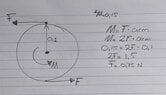
Just a want to have an indication how much torque I need for rotating a plateau with 7.5 kg. See sketch for clearer view.
Hi!

I would like to calculate (roughly) how much torque is needed bringing the blue plateau in movement. Assume the blue plateau is loaded with 7.5 kg. The radius of the blue circle is 100 mm.

1626097074669.png
 
Engineering news on Phys.org
  • #2
Any amount of torque would rotate the disk. So you should set some goal of quantity.
 
  • Like
Likes Mech_LS24
  • #3
Thanks for your reply @anuttarasammyak .

Not any amount would rotate the disk, the disk is loaded with a weight of 7.5 kg. This would give the disk a sort of moment of inertia isn't is? Or do I miss the mark here?

NB. the load is applied in the Z-direction, so actually 'into' the screen.
 
  • #4
Mech_LS24 said:
Not any amount would rotate the disk, the disk is loaded with a weight of 7.5 kg. This would give the disk a sort of moment of inertia isn't is? Or do I miss the mark here?
If the bearings are frictionless, then the rotation will happen with any torque, just more slowly for higher moments of inertia. The relevant equation is ##\tau = I \alpha##

However, if there is bearing friction, you need to overcome the static bearing friction to start the disk rotating. Have you measured the friction of the loaded bearings? Are you using the right type of bearings for the way you are loading the axle?
 
  • Like
  • Informative
Likes crudux_cruo, Lnewqban and Mech_LS24
  • #5
Does the plate rest on a friction free mechanical bearing that keeps it centred ?
or does it rest with friction, like on a bed of sand ?
 
  • #6
berkeman said:
If the bearings are frictionless, then the rotation will happen with any torque, just more slowly for higher moments of inertia. The relevant equation is
If I take an angular acceleration of 3 rad/s^2, the torque needed is:
I= 0.5m*r^2 = 0.5*7.5*100^2 = 50000 kg*mm^2
α = 3 rad/s^2

τ= I*α = 0.05 (kg*m^2) * 3 (rad/s^2) = 0.15 Nm

Ok, this is frictionless.
Can I calculate the angular acceleration to RPM? I can't imagine 3 rad/s^2 yet.

berkeman said:
However, if there is bearing friction, you need to overcome the static bearing friction to start the disk rotating. Have you measured the friction of the loaded bearings? Are you using the right type of bearings for the way you are loading the axle?
I have measured the friction of the bearings yet, this was just a concept. I wanted to know what amount of torque I roughly need for the motor. Maybe as a nice learning process for me I can calculate the static bearing friction for a plain bearing and angular contact bearings?

Using the following reference: Bearing friction coefficients
Angular contact bearings: .0020

Now calculate the torque:
1626156866161.png

P = 7.5kg * 10 = 75 N
μ= 0.0020
dm = 10 mm = 0.01 m (assumption)

Torque = (75N*0.002*0.01m)/2
Torque = 7.5*10^-4 Nm

Do I need to add the torque values for the total torque needed?
 
  • #7
Baluncore said:
Does the plate rest on a friction free mechanical bearing that keeps it centred ?
or does it rest with friction, like on a bed of sand ?
Yep it does rest with friction. I have tried to calculate the friction in post #6. Hopefully on the correct way :)
 
  • #8
Anyone who could support with post #6? Thanks
 
  • #9
Mech_LS24 said:
Anyone who could support with post #6? Thanks
How many alternative situations are you considering? What is, or is not, friction free? What stops things moving sideways? Where are the bearings? What sort of bearings are used?

Just because you put numbers in an equation does not mean the equation is applicable to the situation you had in mind. You must describe the situation and ask the question clearly.

We are not mind readers and won't waste valuable time trying to guess what you do not tell us. Instead we just walk away to escape the confusion, and solve some clearly specified problem elsewhere.
 
  • #10
Thanks for your reply @Baluncore .

Just a want to have an indication how much torque I need for rotating a plateau with 7.5 kg
As mentioned in post #1 I want to have an indication for the needed torque. With this torque I assumed I could select a proper motor.

But (again) as former student and just graduate, I am at the beginning of learning 'new' things. I appreciate you mentioned me on that friction. But you can't expect any magic from me. I shouldn't open this topic if I already knew it. By asking: "does it rest with friction", I can not come with all the things needed for that, because I just doesn't be familiar with that yet.

Now let's try to figure out that friction. I will try to make some sketches and come back to you.
 
  • #11
Does this sketch helps?

Friction_disk.jpg
 
  • #12
I assume that by blue “plateau” you mean a plate, disk, or circle.
I assume that the small white circle marks the fixed centre of disk rotation.
What is the significance of the blue disk 100 mm radius specification?

I assume the black rectangle on the right hand side of the post #1 diagram is a bar that rotates about the fixed white circle.
I assume that the two grey lines are fixed length links that connect the circle to the bar.
I assume that the small red circles mark moving connection pins.
I observe that since the diameter of the blue circle is less than the length of the black bar, the system will be rigid and so cannot rotate.
What is the purpose of the black bar and two grey links?

How much does the blue disk (and shaft)? and outer ball race, and half the links weigh? When you say the blue disk is loaded with 7.5 kg, how is that load arranged and placed? I notice the added load has now risen to 10 kg. Notice that the moment of inertia is dependent on how the mass is distributed over the radius. But if you want to know the torque needed to break the friction then load distribution is not important.

The diameter of the ball centres in the bearing is needed from the data sheet.
What is the part number, 72XX, 73XX, of the angular contact ball bearing ?
 
  • #13
Thanks @Baluncore .

A description of the concept and hopefully it gives a more detailed view for your assumptions, as well I sketched the situation which is visualized below the description:

  • The blue plateau is as disk indeed, this disk carries the load
  • The white points are rotation pivots
  • I specified the radius of 100 mm for the disk, but haven't looked at details here. I can think of the amount of torque in the rods increase by a larger radius. So, if the radius increase, the forces in the rods decreases.
  • The black rectangle is an kind of a transmission for transfer the torque from the motor to the arm which brings the system into 'movement'
  • The red circles are pins which connects the rods from the disk to the motor and vice versa.
  • Good point mentioning the blue disk should be larger as the radius of the black bar. Changed that.
  • The disk is made for example from aluminium, the rods (arm) are most likely made of a steel. So I assume the weight of those parts are in total 1.5 kg. Added to the 10kg makes it 11.5 kg in total.
  • The load is probably loaded equally over the disk, I didn't find a nice way to draw that.
  • The bearing is an 7200 BECBP angular contact bearing. I am not a bearing experts so all recommendations are welcome :)
  • The bearing is locked with a bolt. A disk is pushed through the bolt into the fixed pin.

Please let me know if the description is understandable for you.

Motor_torque_calc_concept.jpg
 
  • #14
Without specifying the distribution of the mass we cannot compute inertia. As I understand it, you only want to know the force needed to initiate movement of the disk. You do not require the rate of disk acceleration.
You need the coefficient of static friction, but the coefficient of dynamic friction is usually specified. I think we must assume the coefficient of static friction will be about twice that specified for dynamic friction. https://en.wikipedia.org/wiki/Friction#Static_friction

The effective radius of the 7200 bearing is (d+D)/4 = 10 mm radius.

Only half the weight of the rods is carried by the 7200 bearing, the other end is carried by the motor bar. You need to itemise the materials list so as to proportionately allocate mass to load the motor bar or the disk.

Since the motor and bar must rotate before the disk, you will also need to know the motor bearing and drive train friction. The motor and bar will transmit a force to the disk through the two rods and four pins. Friction in those rod pin-joints will almost certainly be greater than friction in the 7200 bearing.
 
  • #15
I would like to know the size of motor is needed for a concept like this. Probably I have been at the beginning of this concept been too complacent.

Baluncore said:
The effective radius of the 7200 bearing is (d+D)/4 = 10 mm radius
What is the effective radius? The formula is based on? I got web hits with bolted joints when I search effective radius bearings o_O

Hmm okay regarding the materials list, I take this:
  • Disk: EN-AW6082, t= 5mm, d= 200mm, density = 2700 kg/m^3, weight = 0.42 kg
  • Motor Bar: POM-C, 100x30x8 (L*W*H), density = 1.41 g/cm^3, weight = 0.034 kg
  • Rod: 1.4301 (Stainless steel), d= 10 mm, length = 300 mm, density = 8 kg/m^3, weight = 0.19 kg
  • Bearing 7200 mass = 0.03 kg
Next...?
Static friction (Wikipedia):
{\displaystyle F_{\text{max}}=\mu _{\mathrm {s} }F_{\text{n}}}

Us = 0.75 (assuming steel on steel)
Fn = 100 N (load on the disk) + ((0.42+0.034+(0.19*2)+0.03)*9.81) = 108.5 N

Fmax = 0.75*108.5 = 81.4 N

Baluncore said:
Since the motor and bar must rotate before the disk, you will also need to know the motor bearing and drive train friction. The motor and bar will transmit a force to the disk through the two rods and four pins. Friction in those rod pin-joints will almost certainly be greater than friction in the 7200 bearing.
Shouldn't I first define the motor? Then check the specifications on motor bearing and drive train friction? The pin-joint will probably be with spherical plain bearings, I found the following formula on the SKF site:
M = 0,5 μ P dm
 
  • #16
Mech_LS24 said:
What is the effective radius? The formula is based on?
The inner and outer race thickness are close to equal. So; re = (d+D)/4; is the average of inner and outer diameters, converted to radius, which is the length of the torque arm.
Because mean diameter, dm = 2 * effective radius of the ball race.
M = 0,5 · μ · P · dm ; can be reduced to; M = μ · P · re.

Mech_LS24 said:
Shouldn't I first define the motor?
Specify the type of motor, and select an initial choice. Use the specifications to evaluate that choice in your application.
If you specify a DC servo motor, then the initial torque will be proportional to the initial current, which will simply be; motor voltage divided by motor resistance.
 
  • Like
Likes Mech_LS24
  • #17
Baluncore said:
The inner and outer race thickness are close to equal. So; re = (d+D)/4; is the average of inner and outer diameters, converted to radius, which is the length of the torque arm.
The term 'race' thickness isn't known by me, but I got the message (sketch below).
I was thinking about an TowerPro servo motor, I have used one in the past at school, because it was easy to program with Arduino. I think the motor isn't able to 'move' the load.

I am a bit confused now what I need to consider, the following is the case now(?):
  • Total mass that should be consider is 108.5 N (see Fn in post #15)
  • Bearing is a 7200 angular contact bearing
  • Re for 7200 bearing is 10mm
  • Static friction for the 7200 bearing is 81.4 N (see Fmax post #15)
  • Type of motor is a TowerPro servo motor
  • Output torque of the TowerPro motor is 1.6 kg*cm = 0.16 Nm (I can't find the motor resistance in the specifications..)
  • I take four rod ends to connect the rods from the disk to the servo motor. The rod ends are SI 8 C with dk = re = 13 mm. The frictional coefficient is 0.2 (steel/steel, SKF data).
Given the above I can determine following:
  • The torque for four rod ends (chosen: SI 8 C) are M = μ · P · re (SKF-formula). μ = 0.2 (SKF table, Steel/Steel). So, M = 0.2*108.5(N)*13(mm)*4 = 1.13 Nm

Open questions for me are:
  • The static friction for the 7200 bearing is 81.4 N, how can this be converted into torque? So I can add the static friction with the torque of the rod ends. Yes I know the force times an arm, but which arm should be taken into account?
  • The rod ends comes already with a torque of 1.13 Nm, the TowerPro servo motor can be wiped out
I added a sketch with the updated situation, I try to give you a better view of the situation.

Like to hear.

1626895385973.png
Average_inner_outer.jpg
 
  • #18
Mech_LS24 said:
The term 'race' thickness isn't known by me, but I got the message (sketch below).
The OD of the outer race is the ID of the housing. The ID of the inner race is the OD of the shaft. If you look at a ball bearing in section, (in the SKF data sheet), you will see that the inner and outer races have similar thickness dimensions, as the balls and the two races must fit in the space between the shaft and housing.

The balls all travel in the same circular path. Friction in a ball bearing is not just lubricated rolling, it is also contact between the balls and ball-cage that rotates with the balls at about half the speed of the shaft. The radius to the path of the ball centres is needed to compute torque due to friction from all sources.
https://en.wikipedia.org/wiki/Race_(bearing)
https://en.wikipedia.org/wiki/Ball_bearing

I notice again in your diagram, the rods are not parallel.
They need to be parallel and the same length.
 
  • Like
Likes Mech_LS24
  • #19
Baluncore said:
The OD of the outer race is the ID of the housing. The ID of the inner race is the OD of the shaft. If you look at a ball bearing in section, (in the SKF data sheet), you will see that the inner and outer races have similar thickness dimensions, as the balls and the two races must fit in the space between the shaft and housing.
Very clear, get it. Thanks. Cool process centerless grinding!

Baluncore said:
The radius to the path of the ball centres is needed to compute torque due to friction from all sources.
Thus, I can take the 81.4 N as force and the radius to the path of the ball centre as arm? So:
M = F*arm length
M = 81.4(N)*10(mm) = 814 Nmm = 0.81 Nm

Now I can filter motor with an amount of torque of at least 0.81(Nm) + 1.13 (Nm) = 1.95 Nm. If I add a safety factor of 1.5 makes it, 2.92 Nm.

Correct?

friction_bearing_motor_calc.jpg
 
  • #20
1626895385973-png.png


Baluncore said:
I notice again in your diagram, the rods are not parallel.
They need to be parallel...
Parallel? What am I missing? Somehow I don't see that requirement.

The linkage is configured as a trapezoid, or a 4-bar linkage, which if freestanding is subject to collapse. It is also similar to the configuration of a belt drive with speed reduction (or torque increase).

Cheers,
Tom
 
  • #21
Tom.G said:
The linkage is configured as a trapezoid, or a 4-bar linkage, which if freestanding is subject to collapse.
Don't forget that the centres of the disk and the bar are fixed. The double-rod system is then overconstrained if the rods are not parallel. Think of the parallel connecting rods, in quadrature, on a railway engine.
Tom.G said:
It is also similar to the configuration of a belt drive with speed reduction (or torque increase).
The belt passes around a pully so the length is fixed and the direction is not important. A link attached to a radius arm does change direction as it moves.
 
  • #22
Hmm... To convince myself that the rods must be parallel, I just built a model.

Result was it worked fine with non-parallel links!

It's a bit late for me to to post photos tonight but the model is easy to build.

I tore strips from a 8.5x11 in sheet of paper for the 'hardware', some bent paper clips for the joints, and some straight pins to hold the points of shaft mounting to the carpet. The two links were stacked together and holes poked for the pivot points.

The disk and motor arm had pivot holes at random spacing (see below) and their center points found by folding to align the pivot points. The fold line of course was the center and a straight-edge between the pivot points and a pencil marked the 'shaft' attachment position. (where the straight pins held them to the carpet)

Link spacing on large disk: 7.25in. (18.5cm)
Link length: 7.5in (19cm)
Link spacing on short (motor) arm: 4.25in. (11cm)

Cheers,
Tom
 
  • Skeptical
Likes hutchphd
  • #23
Tom.G said:
Result was it worked fine with non-parallel links!
I can assure you that the rods will be under tension or compression for angular displacements of the short motor bar. For small angles you will not notice it with a pins-in-paper model because it is only a few percent. But a few percent in a mechanism can be destructive, it would certainly build up sufficient force to significantly increase friction in the bearings and pin joints. The motor would not be happy.

I will see if I can give you a numerical example based on your model dimensions.
 
  • Like
Likes hutchphd
  • #24
Code:
' fixed rod = 190 mm
' bar    second
' deg  rod length
'   0  190.000000
'   5  190.033945
'  10  190.138177
'  15  190.317948
'  20  190.581001
'  25  190.938046
'  30  191.403370
'  35  191.995625
'  40  192.738782
'  45  193.663238
'  50  194.806986
'  55  196.216652
'  60  197.948002
'  65  200.065281
'  70  202.638443
'  75  205.737193
'  80  209.421051
'  85  213.725686
'  90  218.647688
 
  • Informative
Likes Tom.G
  • #25
Interesting discussion.

Baluncore said:
Code:
' fixed rod = 190 mm
' bar    second
' deg  rod length
'   0  190.000000
'   5  190.033945
'  10  190.138177
'  15  190.317948
'  20  190.581001
'  25  190.938046
'  30  191.403370
'  35  191.995625
'  40  192.738782
'  45  193.663238
'  50  194.806986
'  55  196.216652
'  60  197.948002
'  65  200.065281
'  70  202.638443
'  75  205.737193
'  80  209.421051
'  85  213.725686
'  90  218.647688
How can I imagine this code? The rod length is increasing by stepping up the degrees, but the rod has a fixed length and thus can't change in length, right?

Mech_LS24 said:
Thus, I can take the 81.4 N as force and the radius to the path of the ball centre as arm? So:
M = F*arm length
M = 81.4(N)*10(mm) = 814 Nmm = 0.81 Nm

Now I can filter motor with an amount of torque of at least 0.81(Nm) + 1.13 (Nm) = 1.95 Nm. If I add a safety factor of 1.5 makes it, 2.92 Nm.

Correct?
Is the approach above correct? As the discussion has skipped this a bit.
 
  • #26
A timing belt has more or less the same structure as the non-parallel rods, does this make sense?

1627064425703.png
 
  • #27
Mech_LS24 said:
The rod length is increasing by stepping up the degrees, but the rod has a fixed length and thus can't change in length, right?
The system is overconstrained, something must give. I fixed one rod at 190 mm, then computed the length of the other needed to close the linkage.
Mech_LS24 said:
A timing belt has more or less the same structure as the non-parallel rods, does this make sense?
Belts remain on the same path, always arrive tangent to the pully, and pass one radius from the centre.
 
  • #28
Mech_LS24 said:
Is the approach above correct? As the discussion has skipped this a bit.
There are problems. Ball bearing friction coefficient is specified by the manufacturer. It has a different value for angular contact than it has for deep groove bearings. The steel balls are rolling along the lubricated steel races, so that is rolling, not steel on steel friction. The ball spacing cage is the source of friction.

The ball ends on the rods are unspecified and will be a source of friction.
Why do you need two solid rods when one will do? Why not use two piano wire links, or strings?
 
  • Like
Likes Mech_LS24
  • #29
Baluncore said:
The system is overconstrained, something must give. I fixed one rod at 190 mm, then computed the length of the other needed to close the linkage.
Did you compute the code in a programming language or so?

Baluncore said:
Belts remain on the same path, always arrive tangent to the pully, and pass one radius from the centre.
For the rods its like, they want to buckle?

Baluncore said:
There are problems. Ball bearing friction coefficient is specified by the manufacturer. It has a different value for angular contact than it has for deep groove bearings. The steel balls are rolling along the lubricated steel races, so that is rolling, not steel on steel friction. The ball spacing cage is the source of friction.
Thanks for the explanation @Baluncore. Unfortunately it is difficult for me to get a feeling for friction. If I am working on concepts, I try to argument what consideration should be taken into account. With a concept like this, I could say as a disadvantage the amount of friction in the rods. Therefore maybe a system with belt/pulley would be the better choice. But always the question remains, what is that amount of friction? A general, simple calculation would help here. But as I understand, friction is a very difficult subject?

Baluncore said:
Why do you need two solid rods when one will do? Why not use two piano wire links, or strings?
I doesn't need two solid rods, but I though this will help decreasing the amount of force on the rods (as shown below). What are piano wire links/strings? Google searches brings me to real piano's :biggrin:
 

Attachments

  • Force_decrease.jpg
    Force_decrease.jpg
    31.8 KB · Views: 98
  • #30
Mech_LS24 said:
Did you compute the code in a programming language or so?
Atached is FreeBasic code = MS VB.
First half is a Linkages Toolkit, last section is the linkage solver for this problem.
 

Attachments

  • Con_Rod_2.pdf
    21.1 KB · Views: 123
  • #31
Baluncore said:
Atached is FreeBasic code = MS VB.
o_O o_O
 
  • #32
The code box for general code was broken, so I used a .pdf file.
I think you should focus on page 3 of Con_Rod_2.pdf
Are you happy with vectors as complex numbers ?
How are you getting on with understanding the modeling of the linkage ?
 
  • #33
Tom.G said:
Result was it worked fine with non-parallel links!

Baluncore said:
I can assure you that the rods will be under tension or compression for angular displacements of the short motor bar.
It strikes me that the main requirement is for the connecting rods be normal to the 'servo' bar at rest. Then any change in angle will be equal and opposite when there is displacement. It's a matter of the dreaded Perpendicular Distance that counts, I think. A possibly better way would be to use a disc on the servo and connect it to the platter with a belt. That would keep the same ratio of torque under all deflection angles. But what error is tolerable? No need to gild the lilly.
 
  • #34
sophiecentaur said:
But what error is tolerable? No need to gild the lilly.
If the error in linkage closure is more than the slack in the linkage, then internal closure forces will greatly increase bearing friction.

sophiecentaur said:
It strikes me that the main requirement is for the connecting rods be normal to the 'servo' bar at rest.
Which suggests that, at least then, they will be parallel.

With only one connecting rod, you can get away with almost anything. But more than one requires that the rod lengths be the same as the distance between the centres of rotation. The radius vector length and direction must be the same at both ends of anyone rod. So the rods will be parallel.

A belt would need to be stepped to maintain the required range of movement. To eliminate hysteresis there must be some belt tension, which adds more unnecessary bearing friction. Stepped belts have significantly higher friction than parallel connecting rods with thin pins.
 
  • #35
Baluncore said:
Which suggests that, at least then, they will be parallel.
Not necessarily. I meant that the bar is replaced by a smaller Vee of two radial bars, so that the force from the rods would be normal then the result of displacement would be to balance the length errors. But it all depends on the permissible slop / error. But what you say about is trapezium, of course, correct
If the whole arrangement were to be made coaxial then there would be no problem at all - excepting the construction, which would possibly need to be better than the OP is suggesting.
Also, I wonder why the drive has to be with two rods. A single rod could be driven by the servo and sit between two pegs on the disc. The rod length would change with angle (Cosine) and friction could be an issue but would it be worse than any of the other proposals?
 

Similar threads

  • Mechanical Engineering
Replies
11
Views
1K
Replies
9
Views
5K
Replies
8
Views
1K
  • Mechanical Engineering
Replies
2
Views
2K
  • Mechanical Engineering
Replies
8
Views
1K
  • Mechanical Engineering
Replies
15
Views
1K
Replies
2
Views
2K
  • Mechanical Engineering
Replies
5
Views
3K
  • Mechanical Engineering
Replies
9
Views
2K
Replies
2
Views
2K
Back
Top