Tracking thermal expansion of an aluminium load cell

In summary, the problem seems to be that the temperature sensor is not very close to the load cell, and the numerical averaging filter is not compensating for the rapid temperature changes.
  • #1
DylanSensor
2
0
TL;DR Summary
I am trying to track the thermal expansion of a load cell in rapidly fluctuating temperatures to predict/model the load cell outputs error in regards to temperature.
Hi all,

I am having trouble getting repeatable results from a linear regression formula that simply uses temperature vs load cell output especially with rapidly increasing/decreasing temperatures.

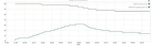
This appears to be a result of the thermal co-efficient of our temperature sensor being almost instant whereas the aluminium load cell appears to take 20-30 minutes before giving stable results. I would like to incorporate the thermal expansion formula with respect to time but having trouble getting my head around it.

PS: Technically a load cell is meant to be a wheatstone bridge which negates the effect of temperature change, this has proven to not be the case on many types of load cells in the application that we are using.

Currently my formula compensates for temperature by adding/subtracting a static value (calculated through a calibration process and using linear regression) per degree of change, however when the temperature changes rapidly, the load cells output does not increase/decrease at the rate at which my formula is compensating for, therefore creating poor results.

Does anyone have any ideas on formulas or methods to help compensate for rapid temperature changes?

Any ideas are appreciated.

Cheers,
Dylan
 
Engineering news on Phys.org
  • #2
DylanSensor said:
Does anyone have any ideas on formulas or methods to help compensate for rapid temperature changes?

Any ideas are appreciated.
Welcome to PF.

1. What is the distance from the temp sensor to the load cell?
2. What causes heating and cooling of the load cell?

Attach the temperature sensor directly to the load cell. Build a foam cover around the load cell and the sensor.

Pass the temp measurements through a numerical averaging filter with the same time constant as the load cell. Then they should track better.
 
  • Like
Likes DaveE, DylanSensor and jrmichler
  • #3
Did you make this load cell? I ask because aluminum is not normally used for load cells. If so, there are two things you can do:

1) Use strain gages that have their TCE matched to aluminum. Micro Measurements has these strain gages: https://micro-measurements.com/linear-pattern-strain-gages. Their transducer class gages may also be available matched to aluminum: https://micro-measurements.com/transducer-class.

2) Mount the temperature transducer adjacent to the strain gages so it measures the actual gage temperature.

Plus what @Baluncore said.
 
  • #4
What does the geometry look like, and where is the temperature changing?
 
  • #5
Hi all,

Thank you for the quick replies!

The temperature sensor is currently on the PCB about 5cm away, we have glued the temperature sensor at the base of the load cell (TAL221) and applied a numerical averaging filter (Taking a measurement every minute and adjusting how many minutes it's averaged over depending on results) but we didn't build much foam/insulation over it out of fear of distorting the load cell as it's in a small cavity with no much wiggle room.

The data sheet indicates its an aluminium alloy, and I've attempted to use it's temperature coefficient SPAN/ZERO however I've not had repeatable results across multiple load cells with the same values (which I wouldn't necessarily expect to).

Here is a datasheet:
https://cdn.sparkfun.com/assets/9/9/a/f/3/TAL221.pdf

Another challenge I am facing is that this device is being designed to operate on different angles, therefore the load cell isn't always in it's ideal orientation. This is by design and a requirement to be fit-for-purpose. It appears some simple trigonometry is solving this, but I'm wary of the effect orientation might have in relation to temperature change (once again theoretically the wheatstone bridge should negate this, but if it's not aligned perfectly I can see how it wouldn't).

Cheers,
Dylan
 
  • #6
Depending on the mounting and load direction details, it may not be load cell errors.

The fact that your corrections are non-repeatable suggests that a wider investigation is needed.

For instance whatever generates/transmits the applied load may be changing shape or dimensions, or have a mechanical interference or geometry problem with temperature. Or even that the wires to the load cell are pulled taught at installation.

(btw, load cells are known to creep, that is they will change output for an extended period of time (hours to days) after a load change.)

Cheers,
Tom
 
  • #7
That style of load cell is sensitive to its mounting. The orientation of the load cell should not affect the calibration, while correctly applying the load is important. Show us a photo of the installed load cell that clearly shows how the load is being applied.
 
  • Like
Likes Tom.G and Baluncore
  • #8
jrmichler said:
That style of load cell is sensitive to its mounting. The orientation of the load cell should not affect the calibration, while correctly applying the load is important. Show us a photo of the installed load cell that clearly shows how the load is being applied.
Hi JR, I am working with Dylan on this. We have the load cells screwed onto a PP mount that is shaped like a triangle. The load cells are mounted at 45 degrees. This is because the box it is in can be positioned either horizontally or vertically. The item we are weighing hangs off a bar straddled between the load cells, sitting on a clip attached to the top of each load cell. We are seeing today that after we tighten the screws, and allow a number of thermal cycles to take place, the load cell loses their accuracy. We have to date been putting this all down to the K factor and had not considered the mounting or tightness of the screws. Would be very interested to have a discussion with you and share some photos.

[Moderator's note: private email address removed.]
 
Last edited by a moderator:
  • #9
samdon1972 said:
We have the load cells screwed onto a PP mount that is shaped like a triangle.
Is PP = polypropylene? If so then it is not surprising it is thermally unstable.
You must attach an aluminium gauge to a rigid aluminium mount.
 
  • #10
jrmichler said:
Show us a photo of the installed load cell that clearly shows how the load is being applied.
I do not like to repeat myself, but this is important for us to be able to help you. Also, it is a subject of general interest to PF members.
 
  • Like
Likes Tom.G
  • #11
jrmichler said:
I do not like to repeat myself, but this is important for us to be able to help you. Also, it is a subject of general interest to PF members.
CAD drawing attached - the prototype mount is made of PETG. The production product will be made of PP. There is not washer etc - they are screwed direct to the mount.
 

Attachments

  • Load Cell Mounting.JPG
    Load Cell Mounting.JPG
    9.2 KB · Views: 146
  • Graph - change in weight with change in temp.JPG
    Graph - change in weight with change in temp.JPG
    18.8 KB · Views: 133
  • #12
Your graph looks like either the plastic or perhaps an adhesive, is cold-flowing at the higher temperature.

Cheers,
Tom
 
  • #13
samdon1972 said:
There is not washer etc - they are screwed direct to the mount.
We must verify that the sensitive axis is independent of the mounting.
1. Why is the strain gauge mounted at a diagonal?
2. How many strain gauges are used?
3. Where is the manufacturer's datasheet for the strain gauge?
 

1. What is thermal expansion?

Thermal expansion is the tendency of a material to change in size, shape, and volume in response to changes in temperature. When a material is heated, its particles vibrate more vigorously, causing them to take up more space and expand. When a material is cooled, its particles move less and take up less space, causing it to contract.

2. Why is it important to track thermal expansion of an aluminium load cell?

Aluminium load cells are commonly used in industrial and scientific applications to measure weight and force. Since aluminium is a metal, it is prone to thermal expansion and contraction. This can affect the accuracy and reliability of the load cell's measurements. By tracking the thermal expansion, we can compensate for any changes in the load cell's dimensions and ensure accurate readings.

3. How is thermal expansion measured in an aluminium load cell?

Thermal expansion in an aluminium load cell is typically measured using strain gauges. These gauges are attached to the load cell and measure the changes in strain (deformation) caused by thermal expansion. The data from the strain gauges can then be used to calculate the thermal expansion coefficient of the load cell.

4. What factors can affect the thermal expansion of an aluminium load cell?

The thermal expansion of an aluminium load cell can be affected by several factors, such as the temperature range it is exposed to, the material composition and purity of the aluminium, and the design and construction of the load cell. Other external factors, such as humidity and pressure, can also influence thermal expansion.

5. How can the data from tracking thermal expansion be used in practical applications?

The data from tracking thermal expansion can be used to calibrate and compensate for any changes in the dimensions of the aluminium load cell. This ensures accurate and reliable measurements, especially in environments with varying temperatures. It can also be used to design more precise and stable load cells for specific applications.

Similar threads

  • Materials and Chemical Engineering
Replies
18
Views
1K
  • DIY Projects
Replies
20
Views
2K
  • Electrical Engineering
Replies
2
Views
606
Replies
4
Views
954
Replies
1
Views
932
  • Materials and Chemical Engineering
Replies
3
Views
3K
  • Mechanical Engineering
Replies
5
Views
2K
  • Electrical Engineering
Replies
8
Views
1K
Replies
15
Views
1K
Replies
3
Views
2K
Back
Top