- #1
Noob of the Maths
- 52
- 6
- Homework Statement
- Circuit 1. Calculates the source voltage, diode and resistance. Plot an I - V curve of the diode and interpret.
Circuit 2. Peak voltages or amplitude taking into account the oscilloscope's v / div scale. Measure the voltage ripple across the load and measure the period, T, taking into account the ms / div scale and thereby calculate the frequency, f of the source voltage.
- Relevant Equations
- Ohm`s law
Hi there!
I have resolve this basic circuit, but, i have a little questions about.
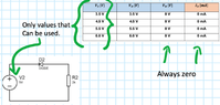
The first circuit its:
 16.34.24.png")
The diode in all voltaje cases act like a switch, so, the courrent of all components and voltage of the resistance its zero. I graph the curve according my interpretation. My question its about if my interpretation its correct.
The second circuit its:
 16.37.34.png")
 16.37.41.png")
 21.47.22.png")
My question its about the values. I obtain it just counter the squares, like the right image.
Thanks 4 read :)
I have resolve this basic circuit, but, i have a little questions about.
The first circuit its:
The diode in all voltaje cases act like a switch, so, the courrent of all components and voltage of the resistance its zero. I graph the curve according my interpretation. My question its about if my interpretation its correct.
The second circuit its:
My question its about the values. I obtain it just counter the squares, like the right image.
Thanks 4 read :)