Understanding Resonance in AC Circuits

In summary: If you are having trouble understanding the material, post a question in the thread and I'll try to help you out. It's really about making your work easy to read. Good handwriting and good photos are also OK.LaTeX isn't necessary, but it is an good way to solve the readability problem. Whether it's here, in school, or in your career, you'll get better results if you make it easy for the people reviewing your work. Look at your posts and imagine that it's you that is being asked to help out; how much effort is in helping, and how much in reading the question.
  • #1
Toky
3
1
Homework Statement
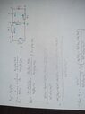
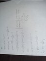
Hello. So, I have an AC circuit in front of me. What I need to do is pull out the formula for inductance of the inductor as L = f(C, R2, w0) and w0 =f(C, R2, L) by calculating the total impedance of the circuit. It's a voltage resonance example so it is supposed to be done by using the term Im(Z)=0. I'm not sure if I did it correctly so I'm asking for help.
Relevant Equations
XL = w0*L
XC = 1/(w0*C)
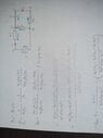
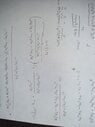
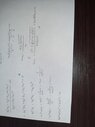
Here's my attempt at a solution.
 

Attachments

  • IMG-20210714-WA0009.jpeg
    IMG-20210714-WA0009.jpeg
    28.3 KB · Views: 123
  • IMG-20210714-WA0009.jpeg
    IMG-20210714-WA0009.jpeg
    28.3 KB · Views: 119
Physics news on Phys.org
  • #2
For some reason, some of the images didn't load properly while constructing the thread, so I'm leaving the full solution in the replies.
 

Attachments

  • IMG-20210714-WA0009.jpeg
    IMG-20210714-WA0009.jpeg
    28.3 KB · Views: 113
  • IMG-20210714-WA0010.jpeg
    IMG-20210714-WA0010.jpeg
    28.7 KB · Views: 110
  • IMG-20210714-WA0011.jpeg
    IMG-20210714-WA0011.jpeg
    27.5 KB · Views: 119
  • IMG-20210714-WA0012.jpeg
    IMG-20210714-WA0012.jpeg
    21 KB · Views: 123
  • #3
Well, the images are coming out small, dim and sideways. It's better to post a PDF file attachment showing the problem statement, and type your work into the forum using LaTeX. See the LaTeX Guide link in the lower left of the Edit window.

While you are learning LaTeX, can you at least post much better/bigger versions of the schematic drawings and seperately post pictures of your work? Be sure to post them upright instead of sideways, and when you attach them, select "Full Size" instead of "Thumbnail". Thanks.
 
  • Like
Likes Toky, hutchphd and SammyS
  • #4
Hard to "decipher" your hand writing. I can only tell you what I get. I get a quite complex expression for Im(Z), but at the end of the day the condition ##Im(Z)=0## simplifies to $$L=C(\frac{1}{C^2\omega^2}+R_2^2)$$ from which I get that $$\omega=\frac{1}{\sqrt{C(L-CR_2^2)}}$$
 
  • #5
Delta2 said:
Hard to "decipher" your hand writing. I can only tell you what I get. I get a quite complex expression for Im(Z), but at the end of the day the condition ##Im(Z)=0## simplifies to $$L=C(\frac{1}{C^2\omega^2}+R_2^2)$$ from which I get that $$\omega=\frac{1}{\sqrt{C(L-CR_2^2)}}$$
Yeah, I cleaned up his last page, and his final result for L looks similar to yours. Can you tell if it is the same? Also, did he work out the expression for ##\omega## ?

1626358065604.png


dim_sideways last page.jpg
 
Last edited:
  • #6
berkeman said:
Well, the images are coming out small, dim and sideways. It's better to post a PDF file attachment showing the problem statement, and type your work into the forum using LaTeX. See the LaTeX Guide link in the lower left of the Edit window.

While you are learning LaTeX, can you at least post much better/bigger versions of the schematic drawings and seperately post pictures of your work? Be sure to post them upright instead of sideways, and when you attach them, select "Full Size" instead of "Thumbnail". Thanks.
I apologise if I've caused any anger or inconveniences. All of my professors ask for 100% hand-written assignments, probably because I'm still only on the 1st year of college, so I never even tried writing in LaTeX, or anything similar, though it seems very convenient. I'll try to learn is ASAP, thanks for the kind advice.
 
  • Like
Likes berkeman
  • #7
Toky said:
I apologise if I've caused any anger or inconveniences. All of my professors ask for 100% hand-written assignments, probably because I'm still only on the 1st year of college, so I never even tried writing in LaTeX, or anything similar, though it seems very convenient. I'll try to learn is ASAP, thanks for the kind advice.
It's really about making your work easy to read. Good handwriting and good photos are also OK.

LaTeX isn't necessary, but it is an good way to solve the readability problem. Whether it's here, in school, or in your career, you'll get better results if you make it easy for the people reviewing your work. Look at your posts and imagine that it's you that is being asked to help out; how much effort is in helping, and how much in reading the question.

It isn't unusual for me, and I suspect others, to simply not comment on a thread that I could help with because it's just too hard to figure out the information I need to assist.
 
  • Like
Likes Toky

1. What is resonance in AC circuits?

Resonance in AC circuits refers to the phenomenon where the inductive reactance (XL) and the capacitive reactance (XC) cancel each other out, resulting in a purely resistive circuit. This causes the current in the circuit to reach its maximum value and the voltage across the circuit to be at its minimum value.

2. How does resonance occur in AC circuits?

Resonance occurs in AC circuits when the frequency of the applied AC voltage matches the natural frequency of the circuit. This causes the voltage across the inductor and capacitor to be in phase, resulting in a maximum current flow through the circuit.

3. What are the applications of resonance in AC circuits?

Resonance in AC circuits has various practical applications, such as in radio and television broadcasting, where the tuned circuits are used to select a specific frequency. It is also used in electronic filters to block or pass certain frequencies and in power transmission systems to reduce energy losses.

4. How does resonance affect the power factor in AC circuits?

Resonance in AC circuits can significantly improve the power factor, which is the ratio of the real power (used to do work) to the apparent power (total power supplied to the circuit). This is because at resonance, the circuit has a purely resistive impedance, reducing the reactive power component.

5. What are the dangers of resonance in AC circuits?

While resonance can have beneficial effects, it can also be dangerous in some cases. When the frequency of the applied voltage is close to the natural frequency of the circuit, the current can become very high, leading to overheating and potential damage to the circuit components. It is important to design circuits with proper damping to prevent resonance from occurring.

Similar threads

  • Engineering and Comp Sci Homework Help
Replies
4
Views
574
  • Engineering and Comp Sci Homework Help
Replies
7
Views
1K
  • Engineering and Comp Sci Homework Help
Replies
2
Views
737
  • Engineering and Comp Sci Homework Help
Replies
8
Views
2K
  • Engineering and Comp Sci Homework Help
Replies
27
Views
2K
  • Engineering and Comp Sci Homework Help
Replies
4
Views
907
  • Engineering and Comp Sci Homework Help
Replies
11
Views
1K
  • Engineering and Comp Sci Homework Help
Replies
1
Views
1K
  • Engineering and Comp Sci Homework Help
Replies
7
Views
897
  • Engineering and Comp Sci Homework Help
Replies
7
Views
2K
Back
Top