Are equivalent resistances wrong in this circuit analysis?

Join the discussion
Registration is free. Start your own thread to ask a follow-up.
11 replies · 4K views · last reply
Hidd
Messages
15
Reaction score
3
Thread moved from the technical forums, so no Homework Template is shown
Hello!

I've took a course about Electrical circuits and Networks at the university, and i found out a problem which is uploaded by my professor, and i think he made a mistake!
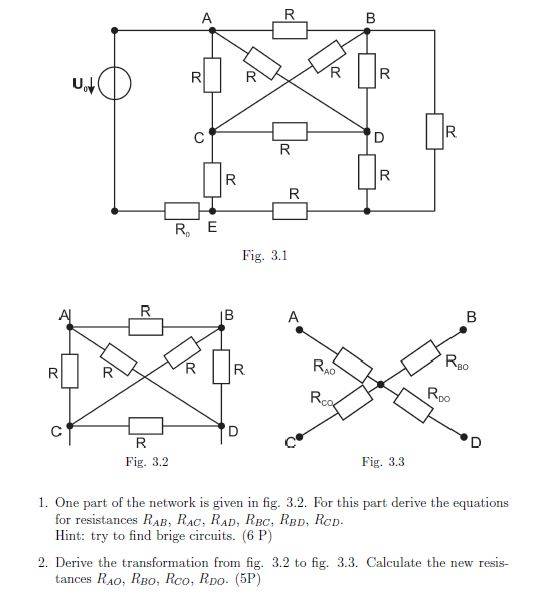
Fig. 3.2: square resistor network with corners A, B, C, D and resistors labelled R on each side and both diagonals, shown beside Fig. 3.3, a crossed-diagonal star-style arrangement with terminals A, B, C, D and resistors R_AO, R_BO, R_CO, R_DO.


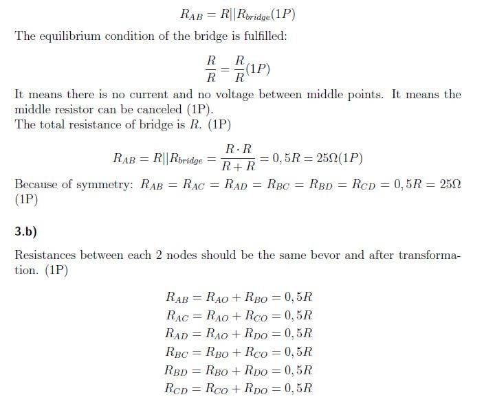
this is the solution

Typed solution of a bridge resistor network: RAB = R||Rbridge, equilibrium condition R/R = R/R, Rbridge = 0.5R = 25 ohms, then six node-pair resistances RAB, RAC, RAD, RBC, RBD, RCD each written as a sum of two star-branch resistances equal to 0.5R.


i think that the equivalent resistances are wrong (beside Rab), for example if you look at Rcd it must be 0, because it's short circuited.
And i coudn't find "the bridge" that he mentioned.

Thanks for help!
All the best,
 
Attachments
  • Fig. 3.2: square resistor network with corners A, B, C, D and resistors labelled R on each side and both diagonals, shown beside Fig. 3.3, a crossed-diagonal star-style arrangement with terminals A, B, C, D and resistors R_AO, R_BO, R_CO, R_DO.
    i3ii4k.jpg
    31.4 KB · Views: 1,487
  • Typed solution of a bridge resistor network: RAB = R||Rbridge, equilibrium condition R/R = R/R, Rbridge = 0.5R = 25 ohms, then six node-pair resistances RAB, RAC, RAD, RBC, RBD, RCD each written as a sum of two star-branch resistances equal to 0.5R.
    10gwl04.jpg
    41.2 KB · Views: 1,453
Physics news on Phys.org
Hidd said:
i think that the equivalent resistances are wrong (beside Rab), for example if you look at Rcd it must be 0, because it's short circuited.
Note that there is no connection "dot" where those wires cross :wink: Every other junction has a dot.
 
  • Like
Likes   Reactions: scottdave and Hidd
gneill, Thank you for your reply and i think you're right! but what about the "bridge"?
we worked on "Wheatstone bridge" which looks like that:
https://www.electronics-tutorials.ws/wp-content/uploads/2013/10/wheatstone1.gif

but i couldn't find similarities with the one that i mentioned earlier!
 
You may need to re-draw your circuit (rearrange the diagram) in order to be able to visualize the bridges. For example, if you remove the resistor that connects node A to node B, then you have:
Circuit schematic with nodes A, B, C and D and resistors R2 to R6; R2 runs from A to C, R5 from B to D, R6 between C and D, and R3 and R4 cross each other diagonally between the two upper junctions and nodes D and C.


Which can be rearranged as:
Circuit schematic of a resistor bridge between terminals A and B, with resistors R2 and R3 in the left branch, R4 and R5 in the right branch, and R6 as the bridge between nodes C and D.


Note that the same resistors still connect to nodes with the same labels; the topology of the circuit is the same as before. Now can you "see the bridge"?
 
Attachments
  • Circuit schematic with nodes A, B, C and D and resistors R2 to R6; R2 runs from A to C, R5 from B to D, R6 between C and D, and R3 and R4 cross each other diagonally between the two upper junctions and nodes D and C.
    upload_2018-2-15_17-38-37.png
    2.2 KB · Views: 825
  • Circuit schematic of a resistor bridge between terminals A and B, with resistors R2 and R3 in the left branch, R4 and R5 in the right branch, and R6 as the bridge between nodes C and D.
    upload_2018-2-15_17-39-15.png
    1.5 KB · Views: 799
  • Like
Likes   Reactions: scottdave and Hidd
You can think of ABCD as a tetrahedron, with resistance R on each of the edges.
I was having a hard time drawing one, so I found an image of one.
Wireframe tetrahedron in pink with vertices labelled A at the top, B on the right, C on the left and D at the bottom front.

Then you can look at it from above A, and project it flat, so A is in the center of the triangle, and it connects outward to B C and D.
 
Attachments
  • Wireframe tetrahedron in pink with vertices labelled A at the top, B on the right, C on the left and D at the bottom front.
    z1bpW8g.jpg
    9.2 KB · Views: 789
  • Like
Likes   Reactions: Hidd
For extra credit. what is the resistance seen by the source Uo in Fig. 3.1 if ALL (including Rd) of the resistors are 50 ohms?
 
@The Electrician. Can I get extra credit for clarifying the diagram and setting the source to one amp ?
LTspice schematic of a resistor network driven by a 1.0A current source I1, with nodes labelled A to E, resistors R1 to R11 each marked {r}, node voltages 97.826087V, 82.608696V, 78.260872V, 71.739128V and 50.000V, directive .tran 1m, and .param r = 50R.
 
Attachments
  • LTspice schematic of a resistor network driven by a 1.0A current source I1, with nodes labelled A to E, resistors R1 to R11 each marked {r}, node voltages 97.826087V, 82.608696V, 78.260872V, 71.739128V and 50.000V, directive .tran 1m, and .param r = 50R.
    Network_R.png
    42.2 KB · Views: 739
For doubleplusgood credit, calculate the resistance from every node to every other node. First number all the nodes in the original network.

Resistor network diagram with nodes numbered 1 to 7 in red, all resistors labelled R; node 1 top left, node 2 top right, nodes 3 and 4 middle, nodes 5 and 6 bottom, node 7 at the bottom left end of a lead.


Then do the math:

Mathematica notebook screenshot: admittance matrix Y as a 7x7 matrix scaled by 1/50, its pseudoinverse Z shown as a fraction matrix, and a 7x7 resistance matrix R with zeros on the diagonal and symmetric values such as 23.478261 and 97.826087.

In the final result matrix the resistance from node j to node k is given by the (j,k) element of the matrix. The resistance from node j to k is, of course, the same as the resistance from node k to node j, hence the matrix is symmetric. And we see all zeroes on the main diagonal because the resistance from a node to itself is zero.
 
Attachments
  • Resistor network diagram with nodes numbered 1 to 7 in red, all resistors labelled R; node 1 top left, node 2 top right, nodes 3 and 4 middle, nodes 5 and 6 bottom, node 7 at the bottom left end of a lead.
    Network.jpg
    9 KB · Views: 655
  • Mathematica notebook screenshot: admittance matrix Y as a 7x7 matrix scaled by 1/50, its pseudoinverse Z shown as a fraction matrix, and a 7x7 resistance matrix R with zeros on the diagonal and symmetric values such as 23.478261 and 97.826087.
    All Resistances.png
    57.9 KB · Views: 1,105
Last edited:
  • Like
Likes   Reactions: scottdave
The Electrician said:
For doubleplusgood credit, calculate resistance from every node to every other node...
Then do the math:

View attachment 221247
I am now curious, since I just went through a Linear Algebra course: what is the key to creating the Admittance matrix by inspection?
 
scottdave said:
I am now curious, since I just went through a Linear Algebra course: what is the key to creating the Admittance matrix by inspection?

 
  • Like
Likes   Reactions: scottdave