Discussion Overview
The discussion revolves around the design and operation of an RLC circuit, specifically focusing on achieving resonant voltage across a capacitor at high frequencies. Participants explore the implications of component values, circuit configurations, and the relationship between impedance and applied voltage.
Discussion Character
- Exploratory
- Technical explanation
- Debate/contested
- Mathematical reasoning
Main Points Raised
- One participant questions the feasibility of using a 0.1 nF capacitor at 100 MHz, suggesting that the capacitance value may be inappropriate for such a high frequency.
- Another participant emphasizes the importance of knowing the resistance value in the circuit, as it directly affects the obtainable voltage across the capacitor.
- A participant mentions the calculated resistance of the capacitor plates as 0.1 Ω and seeks clarification on whether other resistances should be considered.
- Concerns are raised about the necessity of providing a circuit diagram to better understand the setup and resonance coupling.
- Some participants suggest that the user may need to study reactive circuit elements further to clarify their questions and improve understanding.
- One participant provides a calculation for the reactance of the capacitor at 100 MHz, indicating that to achieve 500 V across the capacitor, a significant current would be required.
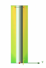
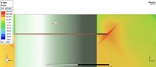
- Another participant discusses the design of a coaxial resonator as a potential solution for generating the required electric field for an ion trap, detailing its structure and function.
- Participants express uncertainty about the optimal circuit configuration (series vs. parallel) and the implications of minimizing resistance to reduce the required applied voltage.
Areas of Agreement / Disagreement
Participants do not reach a consensus on the best approach to design the RLC circuit or the appropriateness of the component values. Multiple competing views and uncertainties remain regarding the circuit configuration and the implications of impedance on voltage requirements.
Contextual Notes
Participants reference specific calculations and theoretical concepts, but there are unresolved questions about the practical implications of component choices and circuit design. The discussion includes assumptions about ideal conditions that may not hold in practical applications.
Who May Find This Useful
This discussion may be useful for individuals interested in RLC circuit design, particularly in high-frequency applications, as well as those exploring the relationship between circuit components and resonance behavior.