cianfa72
- 3,011
- 313
- TL;DR
- The total energy stored in a RLC resonant network feeds from a sinusoidal source should stays at steady-state constant in time
Hi,
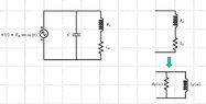
I've a doubt about how to the energy is stored in a 'real' RLC parallel resonant network feeds from a sinusoidal source. Take a 'real' RLC parallel network having a resistor ##R_s## in series with the inductor ##L_s## (modeling its loss) with the capacitor C in parallel and consider it in steady-state at resonance.
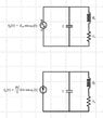
Analyzing the network doing a series-parallel transformation of the couple ##R_s## and ##L_s## into ##R_p## and ##L_p## we can see that the overall energy stored in the RLC network stays constant in time. To prove it just use the following formulas for the Energy of the inductor and capacitor
## E_L(t) = \frac 1 2 L i_L^2(t)## and ## E_C(t) = \frac 1 2 C v_C^2(t)##
then doing the job at ##\omega = \omega_r = \sqrt { \frac 1 {L_sC} - \frac {R^2_s} {L^2_s} }## we can check actually ##E(t) = E_L(t) + E_C(t) = const##
I tried to do the calculation without involving the series-parallel transformation (basically working on the initial RLC network), however this time it seems the total energy stored in the inductor + capacitor is no more constant in time.
The 'problem' here is that we have not anymore a sum of the type ##sen^2(\omega_rt) + cos^2(\omega_rt) = 1## because this time there is an 'phase angle' between the sinusoidal voltage source (emf) and the current through the inductor ##L_s##.
If you want I can add the detail of my job...thank you
I've a doubt about how to the energy is stored in a 'real' RLC parallel resonant network feeds from a sinusoidal source. Take a 'real' RLC parallel network having a resistor ##R_s## in series with the inductor ##L_s## (modeling its loss) with the capacitor C in parallel and consider it in steady-state at resonance.
Analyzing the network doing a series-parallel transformation of the couple ##R_s## and ##L_s## into ##R_p## and ##L_p## we can see that the overall energy stored in the RLC network stays constant in time. To prove it just use the following formulas for the Energy of the inductor and capacitor
## E_L(t) = \frac 1 2 L i_L^2(t)## and ## E_C(t) = \frac 1 2 C v_C^2(t)##
then doing the job at ##\omega = \omega_r = \sqrt { \frac 1 {L_sC} - \frac {R^2_s} {L^2_s} }## we can check actually ##E(t) = E_L(t) + E_C(t) = const##
I tried to do the calculation without involving the series-parallel transformation (basically working on the initial RLC network), however this time it seems the total energy stored in the inductor + capacitor is no more constant in time.
The 'problem' here is that we have not anymore a sum of the type ##sen^2(\omega_rt) + cos^2(\omega_rt) = 1## because this time there is an 'phase angle' between the sinusoidal voltage source (emf) and the current through the inductor ##L_s##.
If you want I can add the detail of my job...thank you
Last edited: