Buck Converter (Step Down Chopper Derivation)

Join the discussion
Ask a follow-up here, or get your own question answered by working scientists, mathematicians and engineers — people, not an autocomplete.
Real named experts · corrections over time · the nuance an AI answer skips
9 replies · 3K views
jaus tail
Messages
613
Reaction score
48
Hi,
I'm studying Choppers and I'm struggling with derivation of Buck Converter.
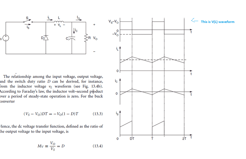
upload_2018-1-3_10-44-20.png

As per equation 13.3 if I solve it ahead I get
Vs D T - Vo D T = - Vo T + Vo D T
Solving this ahead I get
Vs (D T ) = Vo (-T + DT + DT)
Vs (DT) = Vo(2DT - T)
Vs D = Vo (2D - 1)
Vo / Vs = D/(2D - 1)
Not sure how to go ahead from here to reach equation 13.4
 

Attachments

  • upload_2018-1-3_10-37-27.png
    upload_2018-1-3_10-37-27.png
    33.1 KB · Views: 700
  • upload_2018-1-3_10-41-18.png
    upload_2018-1-3_10-41-18.png
    26.5 KB · Views: 608
  • upload_2018-1-3_10-44-20.png
    upload_2018-1-3_10-44-20.png
    27.3 KB · Views: 1,487
Engineering news on Phys.org
There is an error in 13.3. There is no minus sign in front of the Vo on the right-hand side.

You can catch these kinds of errors by visualizing what the equations are telling us physically.
 
But the graph also has - Vo.
Physically area means integrating of V and t.
 
The areas are equal. You can sum them to zero, one contributing positive, the other contributing negative. If they are on opposite sides of the equal sign they will both share the same sign (otherwise they aren't equal).
 
the_emi_guy said:
If they are on opposite sides of the equal sign they will both share the same sign (otherwise they aren't equal).

This is what I don't understand. If they are on opposite side why will both share same sign. Negative Y-axis has negative numbers.
Other book said average voltage for inductor is zero and then they've derived for step down chopper. So I got that through that method.
Like:
V(L during storing) + V(L during releasing) = 0
So (Vs - Vo) Ton - Vo * Toff = 0
This gives derivation.
 
As I said in my first post, you need to see the physical meaning of these equations.

Try putting in real numbers: Say it is a buck regulator dropping 10V down to 1V. Thus Vs = +10V and Vo=+1V.
Where does that lead?
 
  • Like
Likes   Reactions: jaus tail
Sorry I'm not getting it.
I think it can be
Energy store = energy released.
When energy is being stored(load) then input(current entering) is positive terminal. When energy is being released(source) then output(current leaving) is considered positive terminal (kinda like KVL convention)
Thus: (Vs - Vo)Ton = Vo(Toff)

But why V times T and why not V2? Energy is proportional to Voltage square divide by resistance times time.
 
So in steady state, the average inductor voltage is zero. Which means that the sum of the red area + the blue area is zero i.e. $$V_L = \frac{1}{T_s}\int_0^{T_s}v_L(t)dt = 0 $$
Solving the integral we get, which is easy if you look at the figure below:
$$\underbrace{(V_s-V_o)DT_s}_{\text{red area}}+\underbrace{(-V_0)(1-D)T_s}_{\text{blue area}} = 0$$
upload_2018-1-4_14-2-50.png
Then solving as you did in post #1 yields eq. 13.4.

So I am not sure why they included the minus sign in eq. 13.3 as the_emi_guy pointed out in post #2, other than causing confusion.
If you don't know why, the average inductor voltage in steady state has to be zero, look here:
https://www.quora.com/Why-do-inductors-follow-a-volt-second-balance-principle
 

Attachments

  • upload_2018-1-4_14-2-50.png
    upload_2018-1-4_14-2-50.png
    2.2 KB · Views: 579
  • Like
Likes   Reactions: jaus tail and the_emi_guy
Just a correction to my post #8, second equation, should be: $$\frac{1}{T_s}\left[(V_s-V_o)DT_s + (-V_o)(1-D)T_s\right]$$ and not $$(V_s-V_o)DT_s+ (-V_o)(1-D)T_s$$
 
  • Like
Likes   Reactions: jaus tail
Thanks. Got it.
 
  • Like
Likes   Reactions: Baarken