Discussion Overview
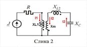
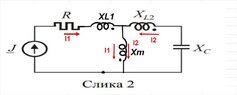
The discussion centers around calculating the power of coils in an RLC circuit, particularly focusing on the behavior of coupled inductors and the implications of their configuration on power dissipation. Participants explore various equations and concepts related to the circuit's operation, including the role of resistance and mutual coupling.
Discussion Character
- Technical explanation
- Mathematical reasoning
- Debate/contested
Main Points Raised
- One participant presents an equation involving currents and reactances but questions the correctness of their results, suggesting that resistance may play a role.
- Another participant emphasizes the absence of real series resistance in coils, arguing that this leads to imaginary power (VAR) rather than real power dissipation.
- Several participants discuss the implications of mutual coupling in the coils and how it affects the equations used to model the circuit.
- There is a suggestion to clarify the location of mutual reactance (Xm) within the circuit, with references to diagrams and previous discussions on coupled inductors.
- One participant expresses uncertainty about the complexity of the topic, indicating that it may exceed their current understanding.
Areas of Agreement / Disagreement
Participants express differing views on the nature of power dissipation in the coils, with some asserting that only reactive power is present due to the lack of resistance, while others explore the implications of mutual coupling. The discussion remains unresolved regarding the exact nature of power in the circuit.
Contextual Notes
There are references to specific circuit elements and configurations that may not be fully defined, leading to potential misunderstandings. The discussion also touches on the complexity of modeling coupled inductors, which may depend on additional assumptions not explicitly stated.
Who May Find This Useful
This discussion may be useful for students and practitioners interested in RLC circuits, coupled inductors, and the analysis of reactive versus real power in electrical engineering contexts.