Calculate the voltage across a resistor using Thevenin's Theorem

Click For Summary

Homework Help Overview

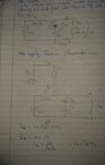
The discussion revolves around calculating the voltage across a resistor using Thevenin's Theorem, particularly in the context of a circuit involving a diode modeled as a switch. Participants are exploring the implications of the diode's state on the circuit analysis.

Discussion Character

  • Exploratory, Assumption checking, Problem interpretation

Approaches and Questions Raised

  • Participants discuss the necessity of determining the diode's state (ON or OFF) to proceed with calculations. There are suggestions to model the diode as a switch and analyze the circuit under different assumptions about its state. Some participants express uncertainty about how to decide the diode's state.

Discussion Status

The discussion is ongoing, with participants offering various approaches to analyze the circuit. There is an emphasis on making assumptions to simplify the problem, and some guidance has been provided on how to approach the analysis based on the diode's behavior.

Contextual Notes

Participants are working under the assumption that the diode behaves as a simple switch, which introduces specific conditions for the circuit analysis. There is a noted lack of clarity on how to definitively determine the diode's state, which is crucial for progressing in the problem.

Andrei0408
Messages
50
Reaction score
8
Homework Statement
The diode in the next figure is considered ideal (i.e. works as a simple switch, being turned ON when U_D >= 0 and OFF when U_D < 0). What is the voltage U_S across R_S?
Relevant Equations
Thevenin's Theorem
I'm thinking I should apply Thevenin's Theorem to find the voltage, but I need to find I_D in order to be able to calculate U_S.
 

Attachments

  • 20210503_215754.jpg
    20210503_215754.jpg
    22.7 KB · Views: 198
Physics news on Phys.org
Andrei0408 said:
I need to find I_D in order to be able to calculate U_S.
You have been told that the diode works as a simple switch. So ##U_D = U_S## if the switch is ON -- never mind ##I_D##. Can you decide it is OFF or ON ?

##\ ##
 
  • Like
Likes   Reactions: Andrei0408
One way to approach this is to substitute your diode model (a switch and a battery) into the circuit. This model has two switch states that have associated restrictions; no forward voltage across the switch when it's open and no reverse current when its shorted. Then you can just pick one state and analyze the circuit in that configuration to determine when the associated restriction is violated. That is the operating point at which the diode will switch states. You can do it with either "on" or "off" assumption, sometimes one is easier to solve than the other.

This approach is a good way to get "unstuck" when you have complex circuits and you don't know where to start. Just make an assumption and get started, but with the knowledge that you may have guessed wrong, then find out if, or under what conditions, you are right or wrong.
 
BvU said:
You have been told that the diode works as a simple switch. So ##U_D = U_S## if the switch is ON -- never mind ##I_D##. Can you decide it is OFF or ON ?

##\ ##
I'm not sure how to do that
 
Pick one and see if it leads to an inconsistency
 

Similar threads

  • · Replies 7 ·
Replies
7
Views
1K
Replies
7
Views
1K
Replies
2
Views
953
  • · Replies 6 ·
Replies
6
Views
2K
Replies
2
Views
2K
  • · Replies 4 ·
Replies
4
Views
2K
Replies
1
Views
1K
  • · Replies 10 ·
Replies
10
Views
3K
  • · Replies 1 ·
Replies
1
Views
1K
  • · Replies 1 ·
Replies
1
Views
2K