Circuit inside DC boost step up pulse power module

8 replies · 9K views · last reply
evan manalu
Messages
3
Reaction score
0
Any one know circuit inside DC boost step up pulse generator?
I have this one buy from ebay 400Kv type,i want to know how this work by circuit inside..
I had googling and not found result..
Please help me..
 
Attachments
  • Black cylindrical potted module with a red wire and a green wire coming out of one end and two twisted red wires out of the other end, photographed on a white background.
    image.jpeg
    22.8 KB · Views: 934
evan manalu said:
Any one know circuit inside DC boost step up pulse generator?
I have this one buy from ebay 400Kv type,i want to know how this work by circuit inside..
I had googling and not found result..
Please help me..
400kV? Is that a typo? What is the application?
 
I'd expect it to at least have a current limiting resistor and a capacitor, like a car ignition. But the nature of the arc makes me think there is more.
 
Right..
More like pulse with modulator..
And i have x-ray scaning
But dificult to identify the component inside
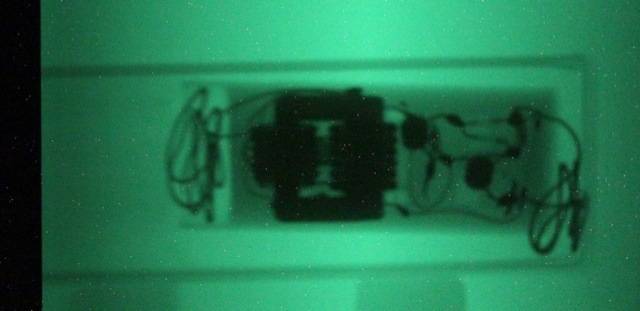
Green-tinted X-ray image of an electronic module showing a large toroidal or coiled component in the centre, several smaller round components on the right and wire leads at the edges.
Greenish X-ray image of an electronic module in a rectangular housing, showing a dark central component with wires and leads looping out at both ends.
 
evan manalu said:
And i have x-ray scaning
But dificult to identify the component inside
Dark silhouette of a PCB-mounted component under green light, with wires looping at both ends, shown on a light tray or board.
The large dark silhouette resembles the EHT transformer from a TV: a square ferrite core with the bulges being two separated windings. The other components would form the oscillator and driver to pulse the primary winding of that transformer.