Tygra
- 55
- 8
Hi there,
I am working on approximate methods to solve for member forces for a multi-storey rigid frame, such as below:

Firstly, I am trying to compute the shears in the columns, and to do this I am using the the shear rigidity given by Stafford-smith and Coull (1991), Tall Building Structures, Analysis and design.
The shear rigidity of an intermediate storey is given by the formula:
$$ GA = \frac{Vh}{\delta} $$
Where:
$$ \delta = \frac{Vh^2}{12EG} + \frac{Vh^2}{12EC} $$
where ## G ## is the flexural stiffness of the beams and is given by:
$$ G = \frac{Ib}{L} $$
and ## C ## is the flexural stiffness of the columns given by:
$$ C = \frac{Ic}{h} $$
This gives the shear rigidity as:
$$ GA = \frac{12E}{h(\frac{1}{G} + \frac{1}{C})} $$
This method assumes that the points on contraflexure occur at the mid height of the columns in the storeys. It very simple for me to understand how we get this equation for ## GA ## and I can derive it easily.
However, the points of contraflexure occurring at mid height of the columns it is not the case for the bottom storey. The points of contraflexure occur approximately ## \frac{2}{3} ## from the base in the bottom storey. For this reason, the equation for shear rigidity is different, and from Stafford-Smith and Coull (1991) the formula for the shear rigidity is given by:
$$ \frac{12E}{h}\frac{ (\frac{2}{3G} + \frac{1}{C})}{ (1 + \frac{C}{6G})} $$
Thus, my question to you is, how was this equation derived? Could someone very clever on this forum attempt to have a go at it? The main reason I want this is because like the bottom storeys, the top storey points of contraflexure do not occur at the mid height. And I want to calculate the shear rigidity at the top storey. Unfortunately Stafford-Smith and Coull to not give the equation for the shear rigidity at the top storey. Once I get this I can proceed with my analysis of approximately calculating the shear in the columns.
EDIT: Important information that needs to be added.
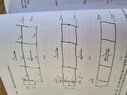
The book my Stafford-smith and Coull provide the following attached diagrams:
The first diagram is the joint rotation due to beam flexure, the second is storey drift due to beam flexure and third is storey drift due to column flexure.
I am working on approximate methods to solve for member forces for a multi-storey rigid frame, such as below:
Firstly, I am trying to compute the shears in the columns, and to do this I am using the the shear rigidity given by Stafford-smith and Coull (1991), Tall Building Structures, Analysis and design.
The shear rigidity of an intermediate storey is given by the formula:
$$ GA = \frac{Vh}{\delta} $$
Where:
$$ \delta = \frac{Vh^2}{12EG} + \frac{Vh^2}{12EC} $$
where ## G ## is the flexural stiffness of the beams and is given by:
$$ G = \frac{Ib}{L} $$
and ## C ## is the flexural stiffness of the columns given by:
$$ C = \frac{Ic}{h} $$
This gives the shear rigidity as:
$$ GA = \frac{12E}{h(\frac{1}{G} + \frac{1}{C})} $$
This method assumes that the points on contraflexure occur at the mid height of the columns in the storeys. It very simple for me to understand how we get this equation for ## GA ## and I can derive it easily.
However, the points of contraflexure occurring at mid height of the columns it is not the case for the bottom storey. The points of contraflexure occur approximately ## \frac{2}{3} ## from the base in the bottom storey. For this reason, the equation for shear rigidity is different, and from Stafford-Smith and Coull (1991) the formula for the shear rigidity is given by:
$$ \frac{12E}{h}\frac{ (\frac{2}{3G} + \frac{1}{C})}{ (1 + \frac{C}{6G})} $$
Thus, my question to you is, how was this equation derived? Could someone very clever on this forum attempt to have a go at it? The main reason I want this is because like the bottom storeys, the top storey points of contraflexure do not occur at the mid height. And I want to calculate the shear rigidity at the top storey. Unfortunately Stafford-Smith and Coull to not give the equation for the shear rigidity at the top storey. Once I get this I can proceed with my analysis of approximately calculating the shear in the columns.
EDIT: Important information that needs to be added.
The book my Stafford-smith and Coull provide the following attached diagrams:
The first diagram is the joint rotation due to beam flexure, the second is storey drift due to beam flexure and third is storey drift due to column flexure.
Attachments
Last edited: