Discussion Overview
The discussion revolves around finding the voltage across a capacitor (Vc) in two different electric circuit scenarios, specifically focusing on circuit analysis techniques. Participants explore the implications of circuit configurations on the behavior of the capacitor in both cases.
Discussion Character
- Technical explanation
- Debate/contested
- Mathematical reasoning
Main Points Raised
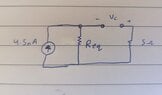
- Some participants assert that the capacitor is not in parallel with the current source in case (a), suggesting a need for recalculation of Vc in both cases.
- In case (b), one participant calculates the Thevenin resistance (Rth) as 15.04 ohms and finds Vc to be 67.68 nV.
- For case (a), another participant mentions that the capacitor acts as a short circuit in a DC circuit, leading to an equivalent resistance (Req) of 7.37 ohms and a voltage of 33.16 nV, but expresses uncertainty about the next steps.
- Some participants agree that the voltage across the capacitor in case (a) should equal the voltage across the 7 ohm resistor and inquire about the current flowing through it.
- One participant describes a method for calculating equivalent resistance in both cases, emphasizing that the capacitor is treated as open-circuited during these calculations.
Areas of Agreement / Disagreement
Participants generally agree on the calculations for case (b) but exhibit disagreement and uncertainty regarding the analysis of case (a), with multiple interpretations of the circuit configuration and its implications for Vc.
Contextual Notes
Participants have not resolved the assumptions regarding the circuit configurations, particularly in case (a), and there are unresolved mathematical steps related to the current through the resistors.