rickyw2777
- 11
- 2
- Homework Statement
- A music filter. Cheap or low-quality audio amplifiers can add noise to an audio recording that is
distracting and undesired. Two examples are a white-noise “hiss” across all frequencies, which
arises from electrons that randomly move inresponse to thermal fluctuations, and a 60Hz “hum”,
which comes from the electrical grid itself (power lines and electrical wires within buildings)
coupling inductively into the circuit.
Our objective is to design an RLC filter to remove these noise sources while allowing the audio
itself (e.g., tones from musical instruments and speech) to get through. The time-series vector 𝑣in
will represent the noisy music, which could be carried on an audio cable from a phone, laptop, or
stereo system, and 𝑣out represents the filtered audio signal from your circuit.
- Relevant Equations
- V_{in}-V_L-V_c-V_R=0;
V_{c,k+1} = V_{c,k} +(h/c)*i_k;
V_{R,k} = i_k*R;
i_{k+1} = i_k +(h/L)*V_{L,K};
Hi, I am trying to build a RLC low pass filter that atenuates the frequency below 4500 Hz. However, I have encountered some problem when choosing the correct R to work with.
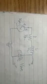
Here is the Circuit

Here is the original sound.

Here is my code in Matlab
function Vout = myFilterCircuit(Vin,h)
n_V = length(Vin);
f_7 = 4470;; % Undesired frequency
h_7 = h; % delta time
% These are for the constant and initialization of the variables
t_7 = 0:h_7:(n_V-1)*h_7; % This is the independent variable
LC_2 = 1/((f_7*2*pi)^2);% This is for L C
R_7 = 0.0001; % This is R
L_7 = 1*10^-3; % This is L
C_7 = LC_2/L_7; % This is C
%
A_2 = [1,h_7/C_7;-h_7/L_7,1-h_7*R_7/L_7]; % This is the A matrix
B_2 = [0;h_7/L_7]; % This is the B matrix
C_2 = [1,0]; % This is the C matrix
D_2 = [0]; % This is the D matrix
%
sys_8 = ss(A_2,B_2,C_2,D_2,h_6); % This is the system
[y_8,tout_8,x_8] = lsim(sys_8, V_inter, t_7); % Simulate the system response
%
Vout = y_8(:,1); % This is the V_c output.
figure;
bode(sys_7, sys_8);
legend('60Hz LPF', '4470Hz LPF');
end
Here is the Bode Diagram

So you can see I used the inductance of 1*10^-3, and capacitance around 1.26*10^-6. I try to use the resistance of 0.0001, but it does not work. And the system of equation eventually becomes not solvable. Please let me know what value of R I should choose.
Here is the Circuit
Here is the original sound.
Here is my code in Matlab
function Vout = myFilterCircuit(Vin,h)
n_V = length(Vin);
f_7 = 4470;; % Undesired frequency
h_7 = h; % delta time
% These are for the constant and initialization of the variables
t_7 = 0:h_7:(n_V-1)*h_7; % This is the independent variable
LC_2 = 1/((f_7*2*pi)^2);% This is for L C
R_7 = 0.0001; % This is R
L_7 = 1*10^-3; % This is L
C_7 = LC_2/L_7; % This is C
%
A_2 = [1,h_7/C_7;-h_7/L_7,1-h_7*R_7/L_7]; % This is the A matrix
B_2 = [0;h_7/L_7]; % This is the B matrix
C_2 = [1,0]; % This is the C matrix
D_2 = [0]; % This is the D matrix
%
sys_8 = ss(A_2,B_2,C_2,D_2,h_6); % This is the system
[y_8,tout_8,x_8] = lsim(sys_8, V_inter, t_7); % Simulate the system response
%
Vout = y_8(:,1); % This is the V_c output.
figure;
bode(sys_7, sys_8);
legend('60Hz LPF', '4470Hz LPF');
end
Here is the Bode Diagram
So you can see I used the inductance of 1*10^-3, and capacitance around 1.26*10^-6. I try to use the resistance of 0.0001, but it does not work. And the system of equation eventually becomes not solvable. Please let me know what value of R I should choose.