How to calculate the electrical power output using the Organic Rankine Cycle?

In summary: For your Rankine cycle calculations, you can simply design a process using a working fluid with a boiling point between your 90 degrees and an assumed runoff cooling medium (probably water) temperature, say 35 degrees C. The maximum efficiency is then already known to be 0.15. This also determines the minimum heat input and thereby the hot water flow rate. In practice, things will be difficult (you'll need driving forces so the actual efficiency will be far worse).I think this kind of hot water use is mainly applied for heating purposes. However, things improve with high-pressure water wells (like in Iceland).Is your question in the context of a homework assignment? If so, then the high-pressure
  • #1
Martin Harris
103
6
TL;DR Summary
Hi
I got a curiosity based on a Geothermal case: depth of the well: 3500m with a temperature of around 90 degrees C at that depth. (I think it will require an ORC cycle, like the primary fluid in the subsurface (collector-pipe) would be the water and at the surface within a 'steam' generator/HE or so, the organic fluid that will quickly vaporize due to its low boiling point.

I want to do sensitivity analysis, such that I can change the length and the flowrate to see how much MWe can get out.
Basically this would be a closed loop geothermal system for electrical power generation. The system would consist of 2 Horizontal Wells connected creating a U-shaped closed loop cycle using thermosiphon effect, with constant recirculation. It's not really a conventional geothermal power generation, more of a ground-source heat pump that generates electricity due to ORC (Organic Rankine Cycle), where water would be heated up, being the primary circulating fluid in the subsurface (geothermal collector - pipe, probably cemented in place), and an organic fluid at the surface that will vaporize quickly turning the turbine and producing electrical power.

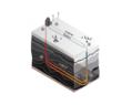
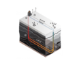
This system would be different from the conventional geothermal power generation due to the fact that in this specific case the geothermal source would act as a heat exchanger, heating up the Well casing and hence the water inside it. (Please see Figure 1 attached below for more details).

Input data:
Well Depth: 3500m
Temperature at that depth: 90 degrees C

Input data that can be adjusted:

Subsurface length: 5000m

Flowrate: I have to figure it out, but this can be adjustable as well.

Casing (geothermal collector piping) outer diameter: this can be adjustable as well: I'd take that initially around 5 in

Organic working fluid type: have to make an assumption here as well, like R134 or Toluene

Output:
x MWe (in the attached Figure, around 2 MWe) by changing the length and the flowrate, have to find x.

My take is that water will flow down the geothermal collector, and I guess the length should not be too small otherwise the water won't heat up enough, and the flowrate shouldn't be too high due to the same reason.

I guess this should be a heat transfer problem, and then I have to figure it out how to generate electrical Power in MW based on the ORC (Organic Rankine Cycle). In the attached figure the electrical power is around 2 MWe, and I'm trying to figure it out how they came up with these calculations.

Any suggestions/guidance on the calculations would be more than appreciated!
 

Attachments

  • Figure1.jpg
    Figure1.jpg
    9.8 KB · Views: 163
Last edited:
Engineering news on Phys.org
  • #2
Didn't you mean 2 vertical wells? If I understand correctly, the Rankine cycle is carried out on ground level. You are transferring heat to the water (which comes from where? and is discharged where?).
 
  • Like
Likes Martin Harris
  • #3
Chestermiller said:
Didn't you mean 2 vertical wells? If I understand correctly, the Rankine cycle is carried out on ground level. You are transferring heat to the water (which comes from where? and is discharged where?).
Hi,
Thanks for the reply, I appreciate it.

Yeah, you could say that they are 2 vertical wells, which are connected horizontally, making a U-closed loop cycle. The horizontal casing (pipes-geothermal collector) are probably cemented in place. Basically two vertical wells several kilometers deep with many horizontal multilateral wellbores several kilometers long.

The geothermal heat source acts as a heat exchanger as far as I understood. Water is being pumped down the well, and it undergoes a closed loop cycle, so it's being recirculated (you can see the process in Figure2 from A->E)
 

Attachments

  • Figure2.png
    Figure2.png
    37.5 KB · Views: 149
Last edited:
  • #4
Those 5 km long horizontal holes will be difficult and expensive to bore.

Maybe consider a horizontal formation of porous sandstone as a heat source. Two vertical wells then provide access to the formation without need for critical underground navigation.

In Australia, energy was extracted from the heat of the artesian flow, but now flow is restricted. You are considering a closed loop or recharge of the aquifer.
https://en.wikipedia.org/wiki/Great_Artesian_Basin
 
  • Like
Likes Martin Harris
  • #5
Baluncore said:
Those 5 km long horizontal holes will be difficult and expensive to bore.

Maybe consider a horizontal formation of porous sandstone as a heat source. Two vertical wells then provide access to the formation without need for critical underground navigation.

In Australia, energy was extracted from the heat of the artesian flow, but now flow is restricted. You are considering a closed loop or recharge of the aquifer.
https://en.wikipedia.org/wiki/Great_Artesian_Basin
Hi,
Thanks for the reply! It's just an example at the moment, I'm trying to get the gist of it.

Figure 2 in post #3 for example has 2.4 km depth and 2km length in the subsurface, indeed I am considering a closed loop system.

In this specific example the geothermal heat source acts as a heat exchanger to heat up the water circulating through the geothermal collector. Then at the surface I think it would require ORC to generate power, since water is like at what? 90 degrees C. I am still trying to figure it out what equations to use to estimate electrical power output in MWe.

I am trying to understand how can electrical power be estimated based on these parameters: depth, temperature at that specific depth (in this case, say 90 degrees C based on the geothermal gradient). I am thinking of performing a sensitivity analysis by changing the subsurface length and water flowrate to see what range of power output in MWe I can get.
 
  • #6
You want to convert heat to power, so you will need some form of cooling to sink waste heat. Your cycle will have a low efficiency (See Carnot cycle) due to the low temperature of the input heat. (Basically the exergy of your hot water is rather low).

For your Rankine cycle calculations you can simply design a process using a working fluid with a boiling point between your 90 degrees and an assumed runoff cooling medium (probably water) temperature, say 35 C. The maximum efficiency is then already known to be 0.15. That also determines the minimum heat input and thereby the hot water flowrate. In practice things will be difficult (you'll need driving forces so actual efficiency will be far worse).

I think this kind of hot water use is mainly applied for heating purposes. Things improve with high-pressure water wells (Iceland).

Is your question in the context of a homework assignment ? If so then the high-pressure alternative is probably not usable.

##\ ##
 
  • Like
Likes russ_watters and Martin Harris
  • #7
BvU said:
You want to convert heat to power, so you will need some form of cooling to sink waste heat. Your cycle will have a low efficiency (See Carnot cycle) due to the low temperature of the input heat. (Basically the exergy of your hot water is rather low).

For your Rankine cycle calculations you can simply design a process using a working fluid with a boiling point between your 90 degrees and an assumed runoff cooling medium (probably water) temperature, say 35 C. The maximum efficiency is then already known to be 0.15. That also determines the minimum heat input and thereby the hot water flowrate. In practice things will be difficult (you'll need driving forces so actual efficiency will be far worse).

I think this kind of hot water use is mainly applied for heating purposes. Things improve with high-pressure water wells (Iceland).

Is your question in the context of a homework assignment ? If so then the high-pressure alternative is probably not usable.

##\ ##
Hello
Thanks for the comprehensive reply!
Indeed, it will have a low efficiency due to water being heated at the maximum temp of 90 degrees C, so yeah low exergy.

Regarding the cooling part, to remove waste heat, I think the chiller will do the job.

Yeah, it looks like a ground-source heat pump to be completely blunt, as the geothermal heat source acts as a heat exchanger, but its purpose is electrical power generation.

It's not for a homework, it's just for my own understanding, it just caught my attention and I became curious about it. I'm trying to figure things out, but at the moment, to be completely honest, I struggle breaking it down into smaller chunks (referring to the equations to be used for the calculation). Any guidance on the equations needed for the calculations would be more than appreciated!
 
  • #8
Martin Harris said:
Any guidance on the equations needed for the calculations would be more than appreciated!
In that case, I recommend that you stop with the Carnot Efficiency limit. That's easy to calculate.
From https://en.wikipedia.org/wiki/Carnot_cycle
1621173131522.png


Caution: absolute temperature means degrees Kelvin.

To go more, like electricity generation, you can't be general. You must be specific as to the method and design of the apparatus to convert the heat to electricity. That could be a year's effort just to figure it out.
 
  • Like
Likes Martin Harris
  • #9
anorlunda said:
In that case, I recommend that you stop with the Carnot Efficiency limit. That's easy to calculate.
From https://en.wikipedia.org/wiki/Carnot_cycle
View attachment 283114

Caution: absolute temperature means degrees Kelvin.

To go more, like electricity generation, you can't be general. You must be specific as to the method and design of the apparatus to convert the heat to electricity. That could be a year's effort just to figure it out.
Hi there!
Thanks for the guidance.
I did calculate the efficiency
η =1 - (35+273.15K)/(90+273.15K), so that's roughly 15.14% as BvU stated.

Now, regarding the electricity generation, I want for the moment just to get the gist of it, a rough estimate, since I'll add complexity later.

Any idea on the steps that should be followed for the power generation estimation?
 
Last edited:
  • #10
Martin Harris said:
the chiller
I missed that in the pictures :rolleyes: ; but you mean the one in the Rankine cycle, of course.

Martin Harris said:
guidance on the equations
There must be plenty (worked out) examples around, or else: a decent textbook on (engineering) thermodynamics (e.g. Cengel) ?

To put together a complete set of equations, you don't care about the exact conditions.

I'm inclined to ask: which component of the setup is the one that causes you problems ?
1621173786084.png
You can't expect us to spell it out for you ? And I think @anorlunda 's one year estimate includes a lot more detail engineering than you need to get an impression.

If you want to work out some detail:
Do you have access to a flowsheeting program ? (e.g. Coco, a freeware simulator)

##\ ##
 
  • Like
Likes Martin Harris
  • #11
BvU said:
I missed that in the pictures :rolleyes: ; but you mean the one in the Rankine cycle, of course.There must be plenty (worked out) examples around, or else: a decent textbook on (engineering) thermodynamics (e.g. Cengel) ?

To put together a complete set of equations, you don't care about the exact conditions.

I'm inclined to ask: which component of the setup is the one that causes you problems ?
You can't expect us to spell it out for you ? And I think @anorlunda 's one year estimate includes a lot more detail engineering than you need to get an impression.

If you want to work out some detail:
Do you have access to a flowsheeting program ? (e.g. Coco, a freeware simulator)

##\ ##
Hi there.
Thanks for the reply.

Well, yeah, I'd need a condenser of some type within the Rankine cycle.

Regarding the complete set of equations, well yeah, I need something generally-ish to get a rough estimate/idea.

But yeah, am not expecting anyone to spell out or so, I am trying to figure out where I can insert the input data that I have such as the subsurface length and the flowrate, which I am not sure how to obtain it. For the flowrate I guess I have to obtain my boiler inlet and outlet conditions and then determine the heat flow available.

Like I have the depth, the geothermal temperature at that depth, and the subsurface length. If I am not using any of these my problem is just plain general.

Regarding which component might cause problems: I guess the turbine
I have Cengel's book for Thermodynamics, and no I'm not familiar with the software Coco, so I have not used it before, but I can give it a try.
 
Last edited:
  • #12
Use of a chiller here is a non-starter: it requires electricity that your power cycle has to provide, and is efficiency depends on the same heat rejection temperature, which as far as I can tell you still haven't provided. It's an overcomplication that doesn't help anything.

So please: what is your heat sink? Ambient air? What is its temperature (and humidity if we are using air)? Once we have that, the calculations are easy.
 
  • Like
Likes Martin Harris and BvU
  • #13
russ_watters said:
Use of a chiller here is a non-starter: it requires electricity that your power cycle has to provide, and is efficiency depends on the same heat rejection temperature, which as far as I can tell you still haven't provided. It's an overcomplication that doesn't help anything.

So please: what is your heat sink? Ambient air? What is its temperature (and humidity if we are using air)? Once we have that, the calculations are easy.
Hi there.

Thanks for the reply, it makes sense, yeah, sorry for the overcomplication.

So, I guess yeah, it can be assumed to use air cooled condenser. As far as I'm aware there are 2 options

a)A literal air cooled condenser where we condense vapour with air
b)A Heller-style system where the condenser with water and then use a giant heat exchanger to cool the water with air

For this example I'd go with a), now I am thinking how can I try to shove the input data from Figure2 below within calculations to obtain electrical power output in MWe, so they won't be silly and plain general.

As for the heat sink, it can be ambient air, yeah, so I guess for simplicity we can assume 25 degrees C, and around 70% humidity, whereas the geothermal source would be at around 90 degrees C, and the inlet water temperature around 35 degrees C.
 

Attachments

  • Figure2.png
    Figure2.png
    37.5 KB · Views: 144
Last edited:
  • #14
Once you know the Rankine design, you know the hot water rate at 90 C required. You then need to determine the size of the pipes underground to deliver that hot water rate, while heating the water to 90 C. You know the buoyant pressure driving force.
 
  • Like
Likes Martin Harris
  • #15
Chestermiller said:
Once you know the Rankine design, you know the hot water rate at 90 C required. You then need to determine the size of the pipes underground to deliver that hot water rate, while heating the water to 90 C. You know the buoyant pressure driving force.
For water I did initially Q = m*cp*delta T.

Basically I assumed that the heat duty in the underground depends on the delta T and on the mass flowrate of water being circulated in the closed loop. The higher the mass flowrate, the bigger the length of the pipe. Delta T and cp can't really be controlled, so just the mass flowrate. Now I have multiple heat duties scenarios based on the mass flowrate variation.

My outer diameter OD of the pipe would be 4.5 inches

A reasonable water mass flowrate in the underground would be around 15 kg/s, but how can I get the length of the pipe for this flow rate?

Then in order to get electrical power output I assumed a conversion factor of about 10% to transform the heat duty intro electrical power output.

Question is, how can I get the length of the pipe based on the water mass flowrate in the underground?

So I have a temperature in the underground of around 90 degrees C, and I will pump down water from an inlet temperature of about 35 degrees C through the pipe with a mass flowrate of about 15 kg/s within a 4.5 inch pipe, to heat it up to 90 degrees C. Now the question is, how can I figure out what length of pipe do I need to accommodate in order to fulfill this process?
 
Last edited:
  • #16
Martin Harris said:
It's not for a homework, it's just for my own understanding, it just caught my attention
I watched the Eavor video commercial and, naturally, they don't dish out the gory technical details.

I get the impression they are able to drill horizontal holes and line them someway to seal them against pressure loss.

Martin Harris said:
Question is, how can I get the length of the pipe based on the water mass flowrate in the underground?
For that million dollar question you will have to do a study of the heat transport. You don't really have a source of 90 ##^\circ##C but an environment that is at that temperature when left alone. If you export heat as you intend to do, the temperature profile will be affected and heat will flow in from greater depths.

For starters you can try to assume the ##\dot Q = U A \ \text {LMTD} \ ## simplification for heat exchanger design. Immediately clear is that if you want those 90 degrees you need a lot of Area :Smile:

And your problem shifts to estimating ##U##. My guess is that the rock-side resistance to heat transfer is a severe limitation. To find out you need to do a simulation wit a heat reservoir at some distance and a haet condcutioon cofficient for the rock, soil, or whatever down there.

For the water side it's easier: see e.g. Coulson and Richardson 6, Ch 12 and take 1000 W/(m2##\cdot ^\circ##C No easy answers (did you expect any?) :wink:

##\ ##
 
  • Like
Likes Martin Harris
  • #17
You need to treat the pipe as a heat sink, immersed in an upward (known) geothermal heat flux coming from below. You need to solve the steady state heat conduction equation based on this known flux and the heat sink rate to determine the ground temperature distribution in the vicinity of the pipe. This will give you the heat transfer coefficient from the ground far-field temperature to the surface of the pipe, and the temperature at the surface of the pipe.
 
  • #18
So far, this was my approach:

I did calculate the cross section as:
A=(Pi*D2)/4 = 15.9 inch2 = 0.01 m2, because my OD (Outer Diameter) was around 4.5 in2
Then I said mass flowrate = density * velocity * cross section
so velocity = mass flowrate / (density*cross section) = 15 kg/s / (1000 kg/m3*0.01 m2)
so water velocity entering the 4.5 inch outer diameter pipe at 35 C would be around 1.5 m/s

Now I was thinking of estimating the time and eventually the length of the pipe. The thing is reaching 90 degrees C seems pretty rough, time consuming. The time will increase exponentially to heat up water from 35 C to 90 C. Like from 35C to 45 C say, it will heat up pretty quick but then it will take longer and longer, since the temperature difference will be smaller and smaller...I'd rather have it at 85 C, rather than wait few more hours to heat it up, and build-up pipe length.

I'm trying to figure it out how can I get the estimated time to heat pumped water at 35 C to say 85C given that the hot source is at 90C, and then figure out the pipe length.

Trying to do this just in a simplistic manner without too many assumptions, just a rough estimate though.
 
Last edited:
  • #19
Martin Harris said:
So far, this was my approach:

I did calculate the cross section as:
A=(Pi*D2)/4 = 15.9 inch2 = 0.01 m2, because my OD (Outer Diameter) was around 4.5 in2
Then I said mass flowrate = density * velocity * cross section
so velocity = mass flowrate / (density*cross section) = 15 kg/s / (1000 kg/m3*0.01 m2)
so water velocity entering the 4.5 inch outer diameter pipe at 35 C would be around 1.46 m/s

Now I was thinking of estimating the time and eventually the length of the pipe. The thing is reaching 90 degrees C seems pretty rough, time consuming. The time will increase exponentially to heat up water from 35 C to 90 C. Like from 35C to 45 C say, it will heat up pretty quick but then it will take longer and longer, since the temperature difference will be smaller and smaller...I'd rather have it at 85 C, rather than wait few more hours to heat it up, and build-up pipe length.

I'm trying to figure it out how can I get the estimated time to heat pumped water at 35 C to say 85C given that the hot source is at 90C, and then figure out the pipe length.

Trying to do this just in a simplistic manner without too many assumptions, just a rough estimate though.
Like I said, you need to determine the heat transfer rate in the ground from the far-field temperature of 90 C to the lower pipe wall temperature as a function of the heat flux to the pipe. You have a steady state heat conduction problem for the ground to solve in the vicinity of the pipe. The size of the thermally disturbed region around the pipe will depend on the heat flow per unit length of pipe and the geothermal heat flux/temperature gradient.
 

1. How does the Organic Rankine Cycle generate electricity?

The Organic Rankine Cycle generates electricity by using a working fluid (usually an organic compound) to absorb heat and vaporize. The vapor then expands through a turbine, which drives a generator to produce electricity.

2. What factors affect the electrical power output of the Organic Rankine Cycle?

The electrical power output of the Organic Rankine Cycle is affected by several factors, including the temperature difference between the heat source and the working fluid, the type of working fluid used, the efficiency of the turbine and generator, and the flow rate of the working fluid.

3. How do you calculate the electrical power output of the Organic Rankine Cycle?

The electrical power output of the Organic Rankine Cycle can be calculated using the equation: P = m * (h1 - h2) * ηturbine * ηgenerator, where P is the power output, m is the mass flow rate of the working fluid, h1 and h2 are the enthalpy values at the inlet and outlet of the turbine, and ηturbine and ηgenerator are the efficiency of the turbine and generator, respectively.

4. What is the efficiency of the Organic Rankine Cycle?

The efficiency of the Organic Rankine Cycle depends on the specific design and operating conditions, but it is typically in the range of 10-15%. This is lower than traditional steam power plants, but the Organic Rankine Cycle can utilize lower temperature heat sources, making it a more versatile option.

5. Can the Organic Rankine Cycle be used for all types of heat sources?

The Organic Rankine Cycle can be used for a variety of heat sources, including geothermal, solar, waste heat from industrial processes, and biomass. However, the specific design and working fluid may need to be optimized for each heat source to achieve maximum efficiency.

Similar threads

  • Engineering and Comp Sci Homework Help
Replies
1
Views
806
  • Advanced Physics Homework Help
Replies
6
Views
1K
  • Engineering and Comp Sci Homework Help
Replies
1
Views
518
  • Engineering and Comp Sci Homework Help
Replies
1
Views
2K
  • Mechanical Engineering
Replies
7
Views
3K
  • Mechanical Engineering
Replies
9
Views
4K
Replies
4
Views
3K
Replies
1
Views
6K
Replies
1
Views
5K
  • Mechanical Engineering
Replies
6
Views
1K
Back
Top